

 English
 中文简体
中文简体RF Coaxial Connectors & Components Manufacturer

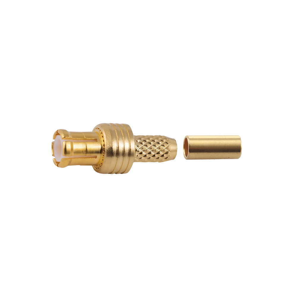
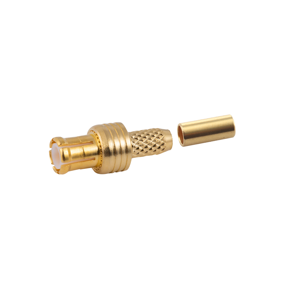
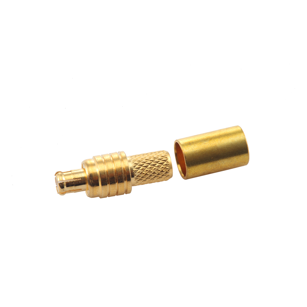
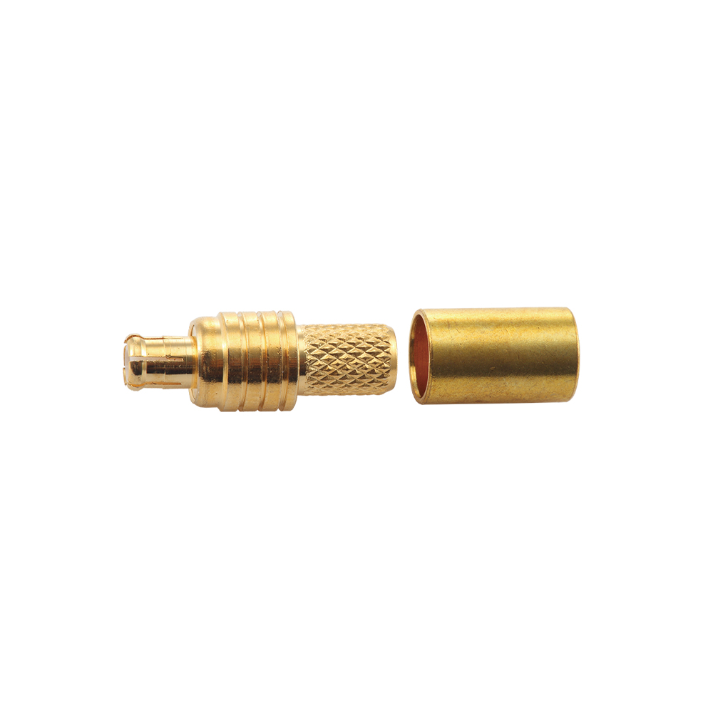
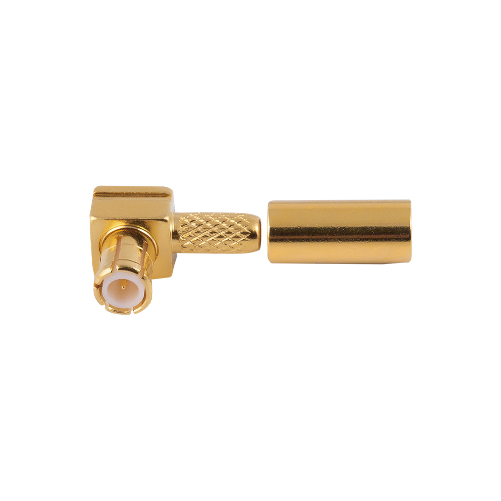
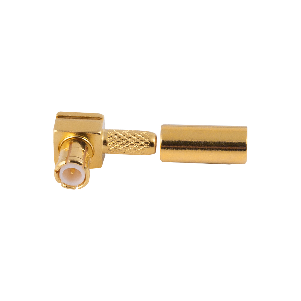
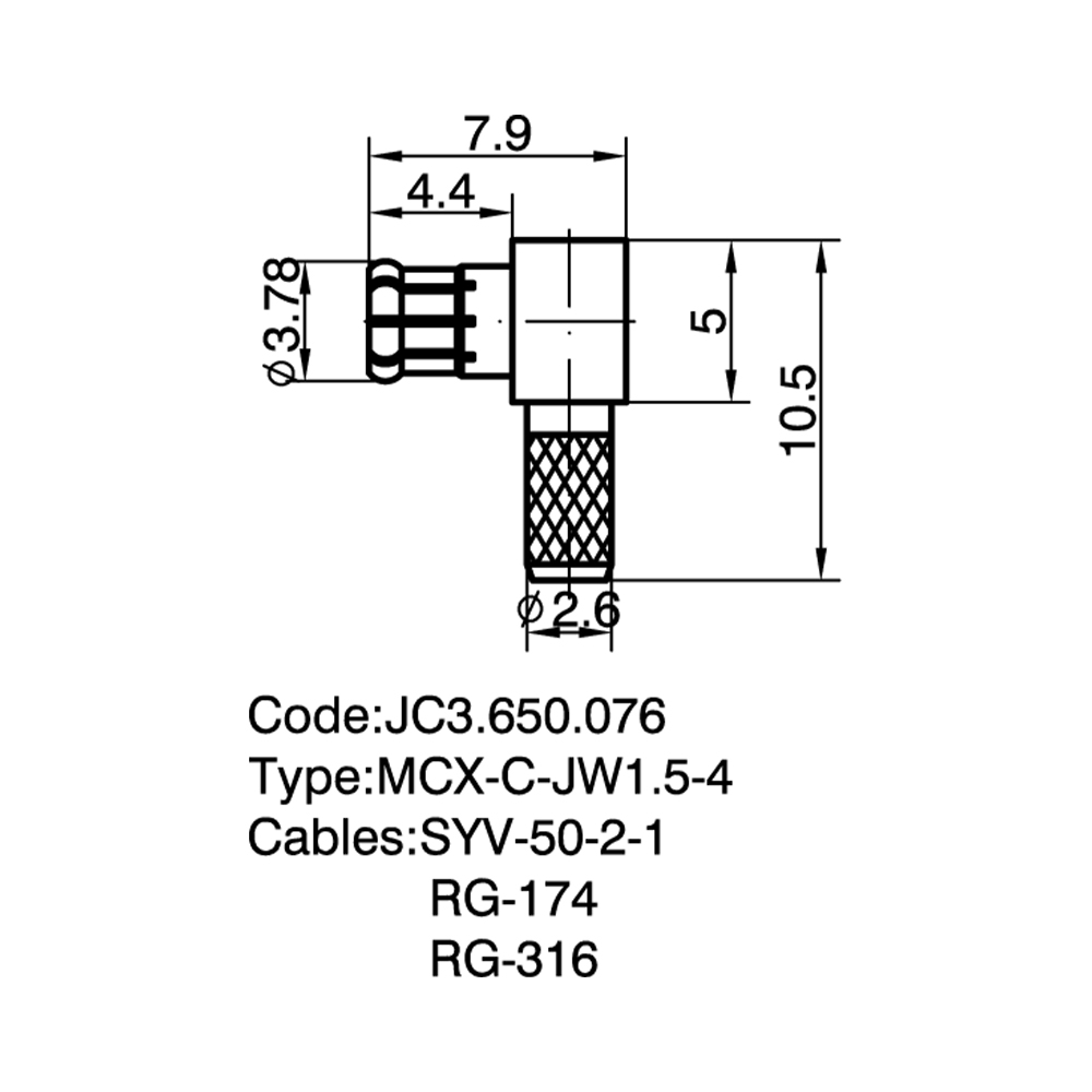
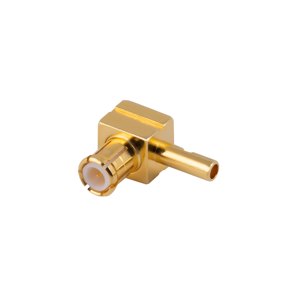
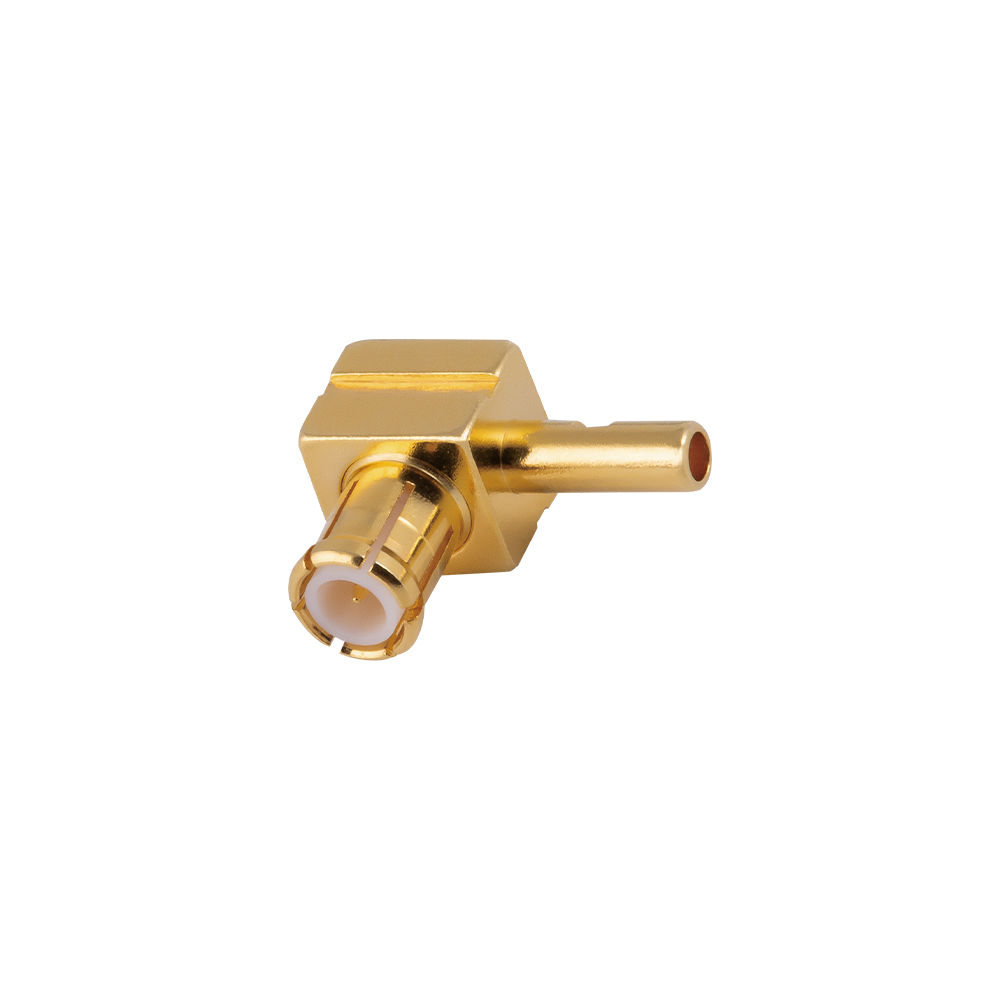
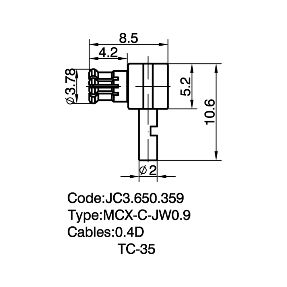
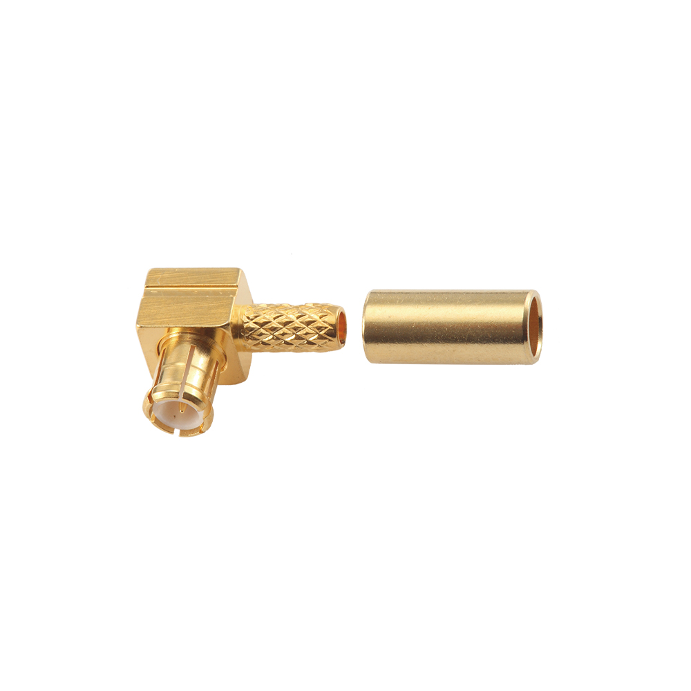
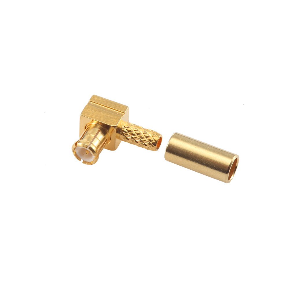
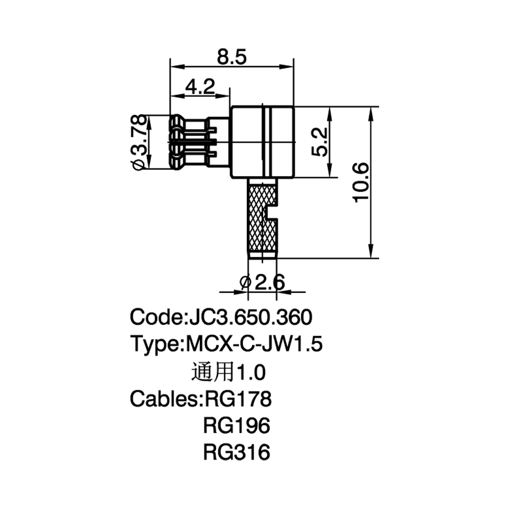
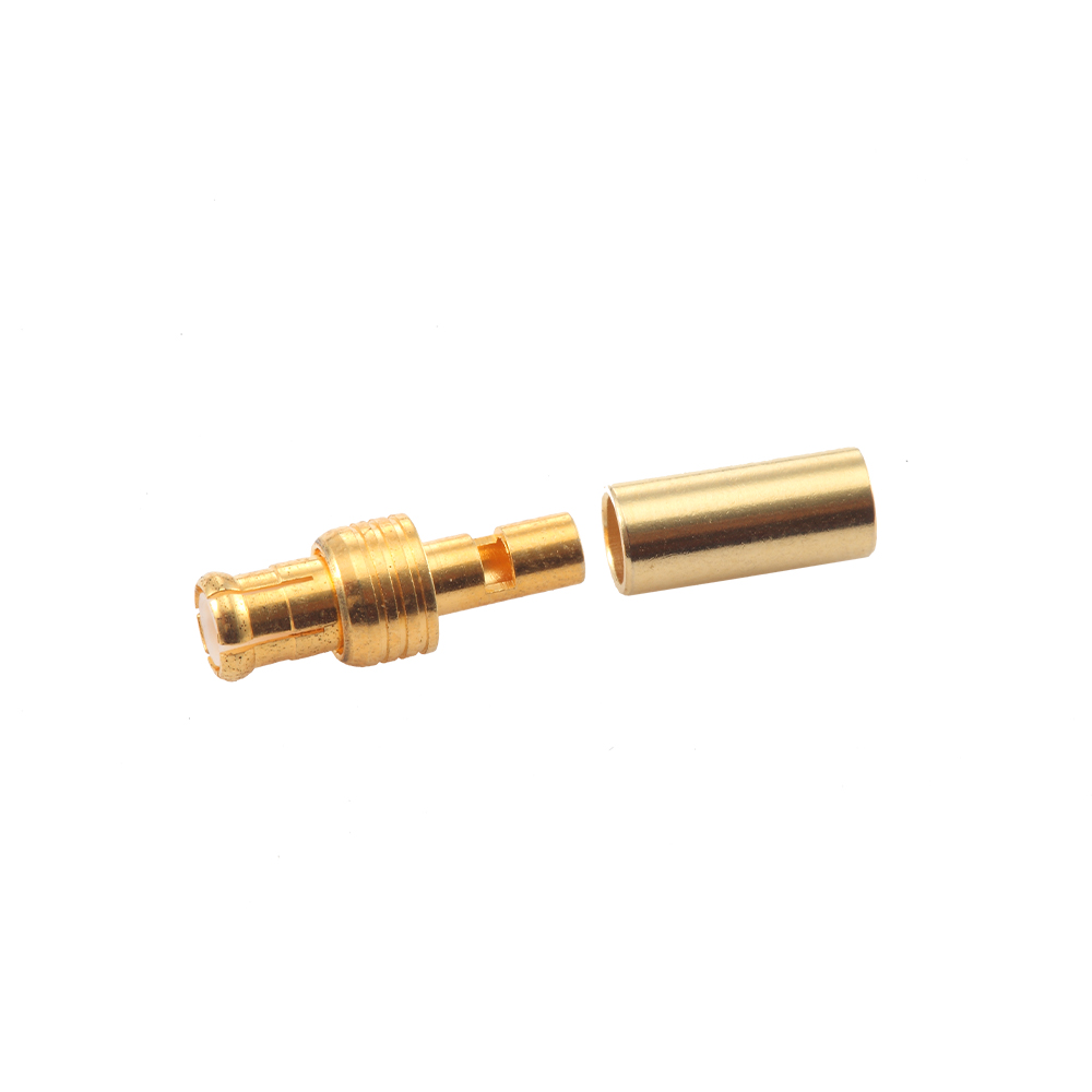
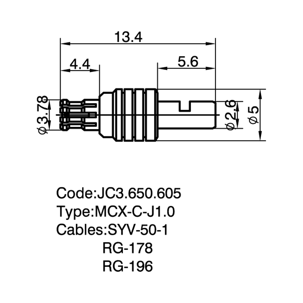
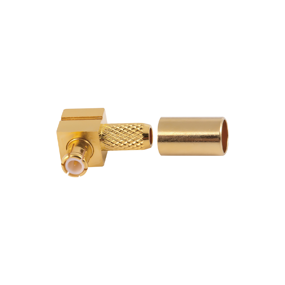
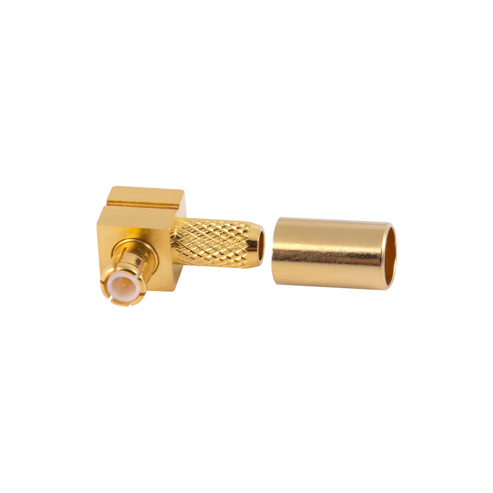
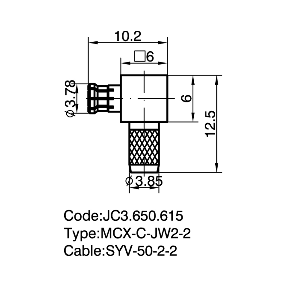
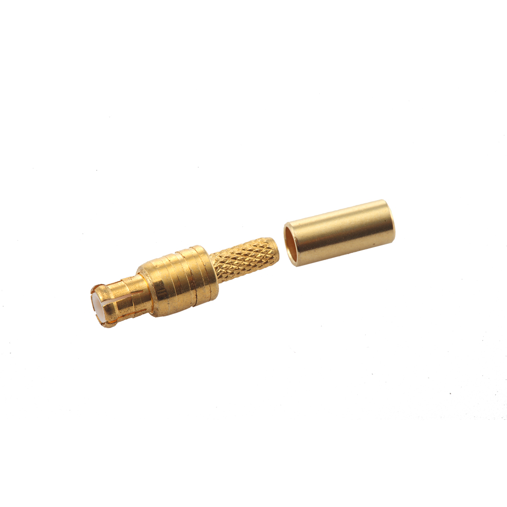
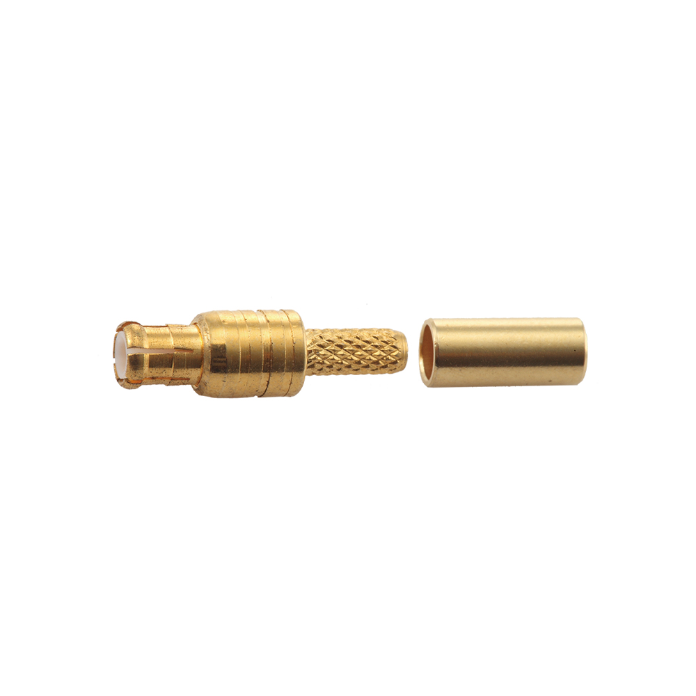
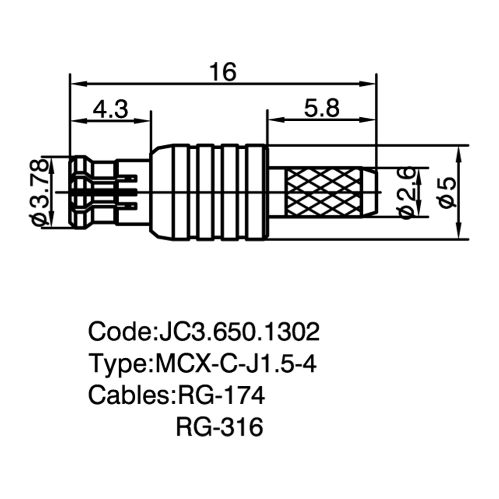
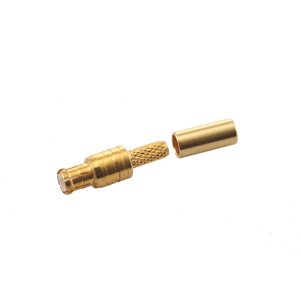
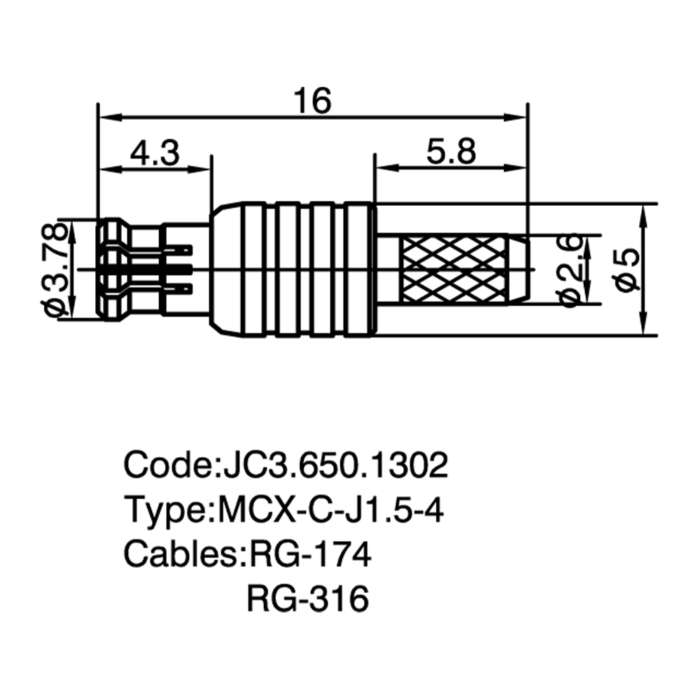

Yangzhou Jingcheng Electronics Co., Ltd., a premier China RF Coaxial Connectors & Components Manufacturer and RF Coaxial Connectors & Components Supplier, was founded in 1999. It is a high-tech enterprise specializing in the R&D and manufacturing of RF coaxial connectors, cable assemblies, and passive microwave components. Equipped with a comprehensive R&D and production system, the company has obtained international certifications including ISO9001. Adhering strictly to standards such as MIL, IEC and GB, we offer over 30 product series with more than 2,000 specifications, covering SMA, BNC, N-type and other mainstream models. Our products are widely applied in the fields of communications, aerospace, automotive electronics and beyond, and exported to many countries and regions across Europe, America and Asia. We uphold the tenet of "Quality as the Foundation, Customers as the Core", committed to providing reliable interconnection solutions and professional services for global clients.
RF Coaxial Connectors & Components form a critical category of interconnect devices engineered to transmit radio frequency signals between coaxial cables, printed circuit boards, antennas, and RF modules with minimal signal degradation. The core function shared across all products in this category is to maintain a consistent characteristic impedance—typically 50 Ω or 75 Ω—along the signal path, thereby preserving signal integrity and minimizing reflections at the interconnection point. These components are designed with a concentric conductor geometry in which an inner conductor is surrounded by a tubular outer conductor separated by a dielectric insulator, a structure that inherently confines the electromagnetic field and provides shielding against external interference.
The defining performance parameters common to RF Coaxial Connectors & Components include frequency range capability (spanning from DC to 50 GHz across different series), voltage standing wave ratio (VSWR) or equivalently return loss, insertion loss, impedance uniformity, and intermodulation performance for high-power or multi-carrier systems. The mechanical attributes—coupling mechanism, durability rated in mating cycles, materials of body and center contact (commonly brass with gold, silver, or nickel plating, and beryllium copper or phosphor bronze for spring contacts), and environmental sealing—are equally critical to reliable long-term operation. Yangzhou Jingcheng Electronics Co., Ltd. supplies a comprehensive portfolio within this category, encompassing precision connector series and associated components manufactured with advanced CNC machining and high-precision testing equipment to meet the demands of modern RF systems.
A key advantage of this product category is the breadth of standardized interface designs available, each optimized for specific frequency ranges, power levels, and mechanical constraints. From subminiature push-on types for dense board-level layouts to robust weather-resistant connectors for outdoor infrastructure, RF Coaxial Connectors & Components provide the essential building blocks for constructing reliable RF signal chains in telecommunications, test and measurement, aerospace and defense, automotive radar, medical imaging, and industrial IoT systems.
The following table summarizes the most widely used RF coaxial connector series, their defining electrical and mechanical characteristics, and their typical deployment scenarios. This comparison aids in understanding the differentiation among interface standards within the broader classification.
| Connector Series | Impedance | Max Frequency | Coupling Type | Key Characteristics | Typical Applications |
|---|---|---|---|---|---|
| SMA | 50 Ω | 18 GHz (standard) 26.5 GHz (precision) |
Threaded | Compact, durable, stainless steel option available, wide industry adoption | Cellular base stations, Wi-Fi equipment, test instrumentation, GPS modules |
| 3.5 mm / 2.92 mm | 50 Ω | 34 GHz / 40 GHz | Threaded | Air-dielectric interface, high-precision, SMA-compatible (3.5 mm), low VSWR at mmWave | Millimeter-wave testing, 5G backhaul, satellite communication, radar systems |
| 2.4 mm / 1.85 mm | 50 Ω | 50 GHz / 67 GHz | Threaded | Highest precision in this category, ruggedized air-dielectric design, laboratory-grade | Network analyzers, high-frequency R&D, aerospace telemetry, 5G mmWave |
| SMP | 50 Ω | 40 GHz | Push-on / Snap-on | Blind-mate capable, axial/radial float tolerance, high packaging density | Phased array antennas, military avionics, dense board-to-board RF links |
| MCX / MMCX | 50 Ω / 75 Ω | 6 GHz | Snap-on | Ultra-miniature footprint, quick connect/disconnect, lightweight, 360° rotation (MMCX) | GPS receivers, handheld radios, IoT devices, automotive telematics, PCB connectors |
| BNC | 50 Ω / 75 Ω | 4 GHz (standard) 10 GHz (precision) |
Bayonet | Quick-lock bayonet coupling, robust, widely recognized, low cost | Broadcast video, test equipment, medical monitors, legacy RF systems |
| TNC | 50 Ω | 11 GHz | Threaded | Vibration-resistant threaded version of BNC, weatherproof options available | Mobile communications, antenna feeder lines, outdoor wireless infrastructure |
| N-Type | 50 Ω / 75 Ω | 11 GHz (standard) 18 GHz (precision) |
Threaded | High power handling, weather-resistant, durable threaded interface, large diameter | Base station antennas, broadcast transmitters, high-power RF systems, outdoor installations |
| DIN 7/16 | 50 Ω | 7.5 GHz | Threaded | Very high power capacity, low PIM, robust mechanical design, large contact area | Cellular tower jumpers, high-power combiners, broadcast transmission lines |
| UHF | Non-constant | 300 MHz | Threaded | Legacy design, large form factor, high voltage tolerance, economical | Amateur radio, low-frequency RF, public address systems, legacy equipment |
Note: Frequency ratings represent typical maximum values for precision-grade connectors. Actual performance depends on connector design, materials, plating quality, and cable assembly workmanship. Yangzhou Jingcheng Electronics Co., Ltd. produces these connector series with rigorous quality control to achieve specified electrical performance across the rated frequency range.
RF coaxial connectors and components are deployed across a diverse range of industries. The selection of an appropriate connector series is driven by the specific electrical, mechanical, and environmental requirements of each application domain.
Base station feeder connections (DIN 7/16, N-Type), small cell backhaul (SMA, 2.92 mm), distributed antenna systems, and 5G massive MIMO arrays (SMP, SMZ). Low PIM performance is critical for multi-carrier cellular systems.
Vector network analyzers, spectrum analyzers, and signal generators rely on precision-grade connectors (2.4 mm, 1.85 mm, 2.92 mm) with calibrated electrical characteristics for accurate measurements up to 50 GHz and beyond.
Radar systems, satellite communication terminals, electronic warfare equipment, and avionics. Connectors must meet stringent requirements for vibration resistance, wide temperature range, and high reliability (SMP, SMA, TNC, 2.92 mm).
GPS antennas (MCX, SSMB), V2X communication modules, automotive radar (SMA), telematics control units, and industrial IoT sensor nodes requiring compact, lightweight interconnects with reliable snap-on engagement.
Broadcast video transmission (BNC 75 Ω), MRI coil connections, patient monitoring equipment, and diagnostic imaging systems where signal fidelity and connector reliability are paramount.
Choosing the correct RF coaxial connector or component requires systematic evaluation of the following parameters to ensure optimal electrical performance and mechanical compatibility within the target system.
| Selection Parameter | Guidance |
|---|---|
| Frequency Range | The connector's maximum rated frequency must exceed the highest operating frequency of the system. For harmonics or wideband signals, include adequate margin. Precision connectors (2.92 mm, 2.4 mm, 1.85 mm) are specified for millimeter-wave bands. |
| Characteristic Impedance | Match the system impedance—50 Ω for most wireless, cellular, and test applications; 75 Ω for broadcast video and CATV distribution. Mismatched impedance causes reflections and increased VSWR. |
| Power Handling | High-power transmitters require connectors with larger contact diameters and robust dielectric materials (DIN 7/16, N-Type). Exceeding power ratings leads to overheating, arcing, and premature failure. |
| Coupling Mechanism | Threaded (SMA, N, TNC, DIN) for vibration resistance and consistent torque; bayonet (BNC) for quick connect/disconnect; snap-on/push-on (MCX, MMCX, SMP) for high-density and blind-mate scenarios. |
| Environmental Sealing | Outdoor installations require IP-rated connectors with gaskets and weatherproof boots. Indoor and laboratory environments may accept non-sealed interfaces. |
| Mating Cycles | Laboratory-grade connectors are rated for thousands of mating cycles with consistent electrical performance. Field-deployed connectors may prioritize robustness over high cycle count. |
| PIM Requirements | For cellular infrastructure, select low-PIM connectors (DIN 7/16, specific N-Type variants) with appropriate plating and contact design to minimize passive intermodulation distortion. |
Beyond connectors, the RF Coaxial Connectors & Components classification encompasses a range of passive devices that perform essential functions within RF signal chains. These components are engineered with the same precision and impedance-controlled design principles as the connectors themselves.
Fixed and variable attenuators reduce signal amplitude by a specified dB value while maintaining impedance matching. Used for level control, isolation improvement, and receiver protection in test setups and live systems.
Precision 50 Ω or 75 Ω terminations absorb RF energy to prevent reflections at open ports. Essential for terminating unused ports on couplers, dividers, and antenna switching matrices.
Gas-discharge or quarter-wave stub protectors that shunt high-voltage transients to ground, safeguarding sensitive RF equipment in outdoor antenna installations from lightning-induced surges.
In-series and between-series adapters enable interconnection of dissimilar connector types. Reverse polarity variants provide gender-reversed center contacts for compliance with specific regulatory standards (FCC Part 15).
Factory-terminated coaxial cable assemblies with guaranteed VSWR and insertion loss performance. Available in flexible, semi-rigid, and conformable cable types for DC to 50 GHz applications.
The impedance value refers to the characteristic impedance of the connector's transmission line structure, determined by the ratio of inner conductor diameter to outer conductor diameter and the dielectric constant. 50 Ω is the standard for most wireless, cellular, and test equipment, offering an optimal balance between power handling and low attenuation. 75 Ω is predominantly used in video broadcast, CATV, and satellite TV distribution where minimum signal loss over long cable runs is prioritized. The two impedance standards are not directly interchangeable—mating a 50 Ω connector with a 75 Ω counterpart creates an impedance discontinuity that increases VSWR and signal reflections, degrading system performance. Some connector series (BNC, N-Type, MCX) are manufactured in both 50 Ω and 75 Ω versions, so verifying the impedance rating before interconnection is essential.
The maximum frequency rating of a connector is determined by its physical dimensions and the dielectric material used. As frequency increases, the wavelength becomes shorter, and the connector's internal geometry begins to support higher-order propagation modes that distort the intended TEM mode, causing resonances and increased insertion loss. For applications above 18 GHz, precision connectors such as 2.92 mm (40 GHz), 2.4 mm (50 GHz), and 1.85 mm (67 GHz) are specified because their smaller cross-sectional dimensions push the cutoff frequency of unwanted modes well beyond the operating range. SMA connectors, while rated to 18 GHz in standard form, can be manufactured in precision grades reaching 26.5 GHz. Selecting a connector with insufficient frequency headroom results in degraded VSWR and unpredictable performance at the upper end of the operating band.
Push-on (snap-on) connectors such as SMP, MCX, MMCX, and SSMB offer several operational advantages: faster mating and unmating without tools, reduced installation time in high-volume manufacturing, the ability to accommodate axial and radial misalignment (particularly SMP with its floating bullet design), and suitability for blind-mate applications where visual access to the connector interface is limited. The trade-off is that push-on connectors generally provide lower retention force than threaded interfaces and may be more susceptible to accidental disconnection under severe vibration unless additional retention features are incorporated. Threaded connectors (SMA, N-Type, TNC, DIN) remain the preferred choice for high-vibration environments and applications where connection integrity is critical.
Passive intermodulation occurs when two or more transmitted carriers mix at nonlinear junctions within passive components—including connectors, cables, and adapters—generating spurious signals at sum and difference frequencies that can fall within the receiver band. In cellular base stations, even low-level PIM products can desensitize receivers and reduce uplink capacity. Connectors designed for low-PIM performance (such as DIN 7/16 and specially plated N-Type variants) use materials with minimal ferromagnetic content, high-contact-pressure designs, and consistent plating thickness to minimize nonlinear effects. PIM specifications, typically measured in dBc at two 20W tones, are a critical selection criterion for connectors deployed in multi-carrier cellular and distributed antenna systems.
The production of high-performance RF coaxial connectors requires precision CNC machining with tight tolerances (often within microns) for center contact concentricity and interface dimensions, along with controlled plating processes for conductivity and corrosion resistance. Yangzhou Jingcheng Electronics Co., Ltd. employs advanced manufacturing equipment and high-precision testing instruments—including vector network analyzers capable of characterizing VSWR and insertion loss across the full rated frequency spectrum—to verify that each connector series meets its specified electrical and mechanical parameters. In-house testing capabilities spanning DC to 50 GHz ensure that products including 2.92 mm, 2.4 mm, 1.85 mm, SMP, SMA, BNC, TNC, N, DIN, MCX, MMCX, and associated cable assemblies, attenuators, terminations, and lightning arresters are delivered with verified performance data.
RF Coaxial Connectors & Components represent a foundational interconnect technology for radio frequency systems, with performance directly influencing signal integrity, system reliability, and measurement accuracy. The selection of an appropriate connector series—guided by frequency requirements, impedance matching, power handling, environmental conditions, and mechanical constraints—is an engineering decision that benefits from a thorough understanding of the characteristics documented above. The comprehensive portfolio available from Yangzhou Jingcheng Electronics Co., Ltd., encompassing precision connector series from DC to 50 GHz along with attenuators, terminations, lightning arresters, adapters, and cable assemblies, provides solutions for applications ranging from high-volume wireless infrastructure to precision laboratory instrumentation.



Copyright © Yangzhou Jingcheng Electronics Co., Ltd.All Rights Reserved. China RF Coaxial Connectors & Components Manufacturer RF Coaxial Connectors & Components Supplier
