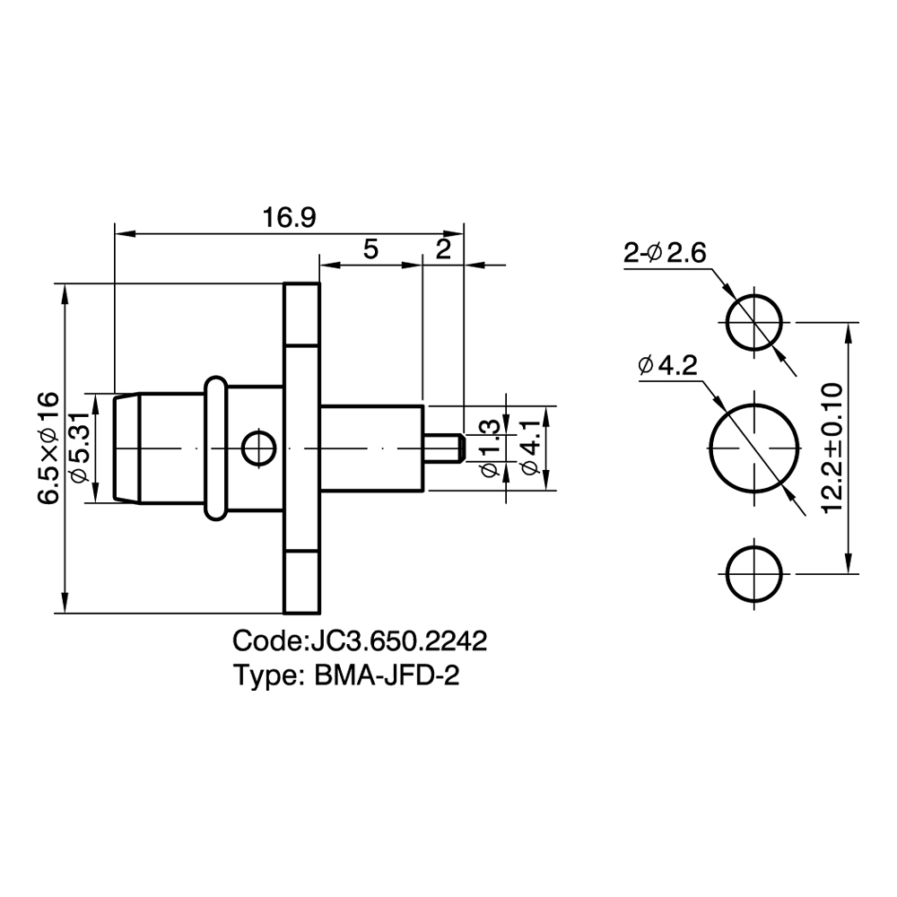
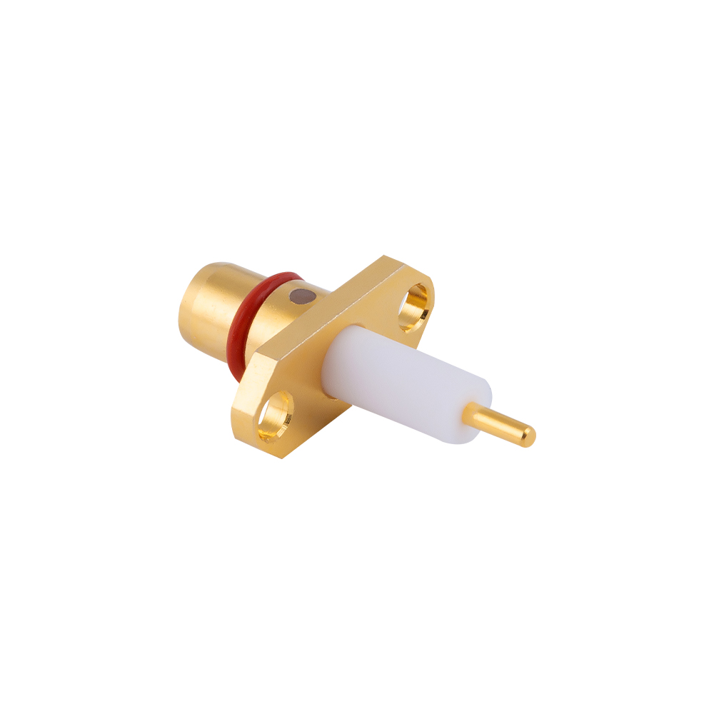
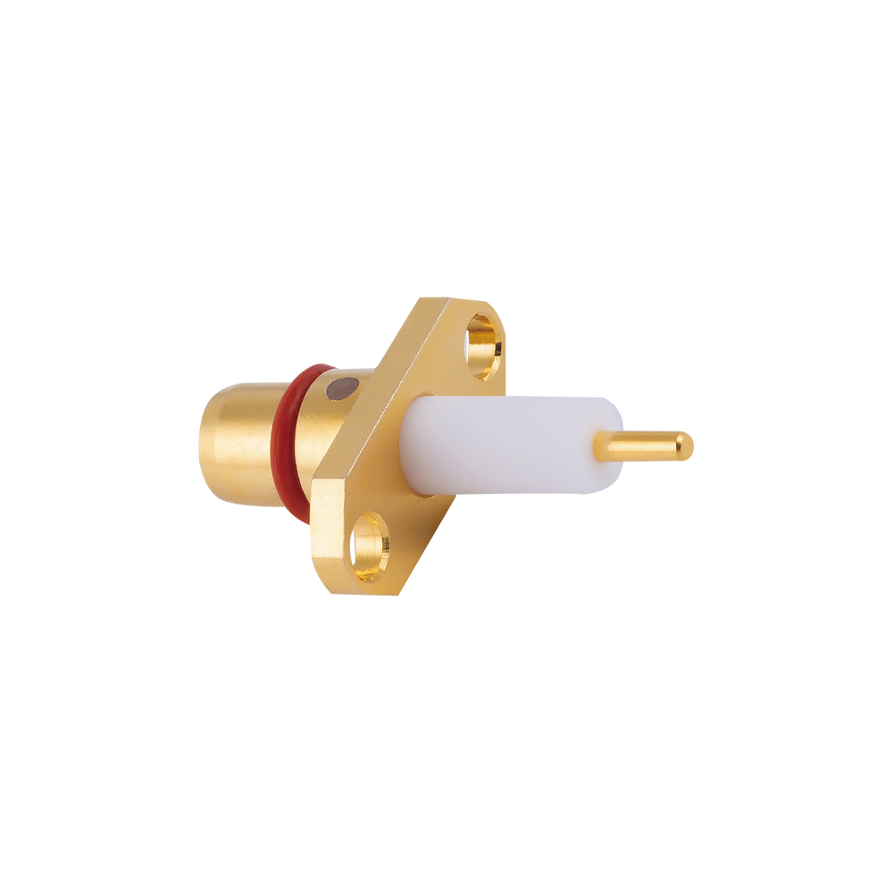
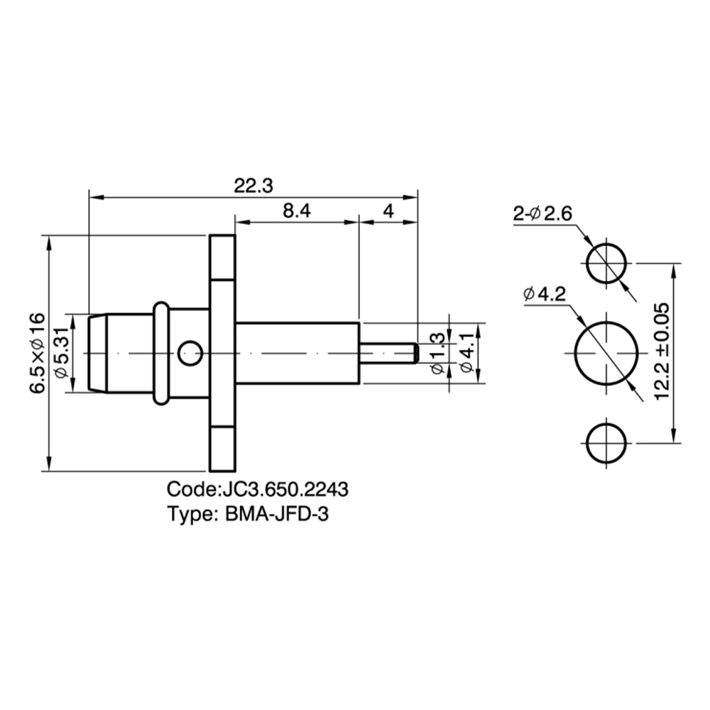
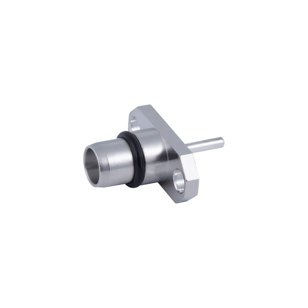
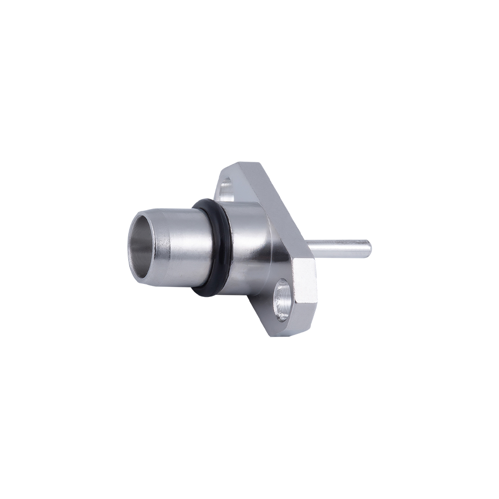
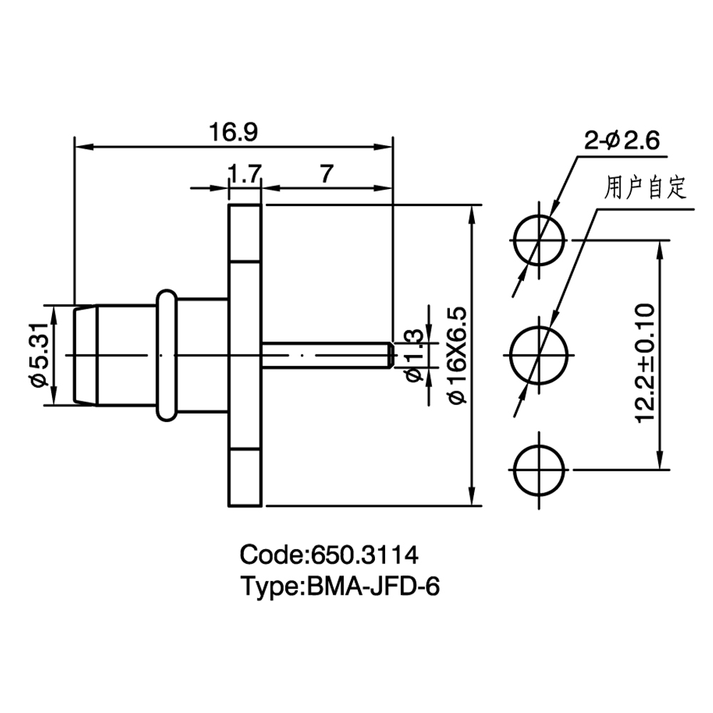
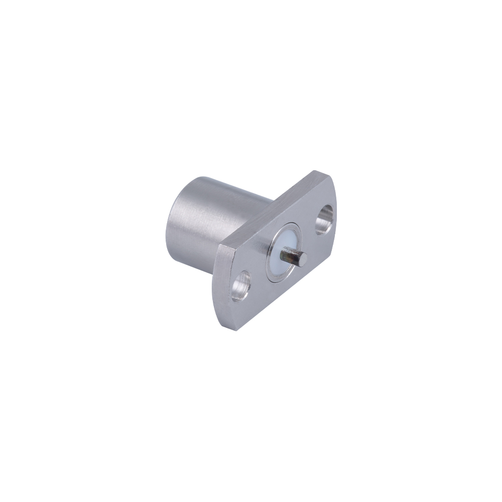
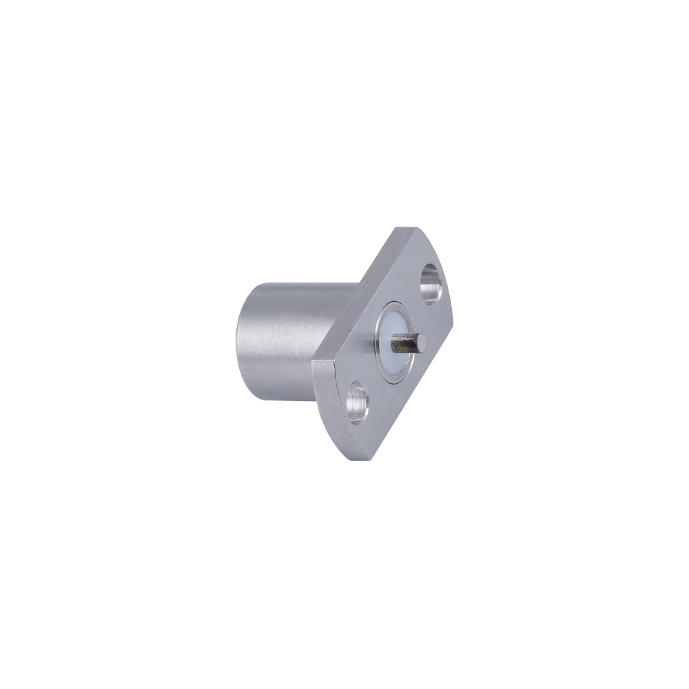
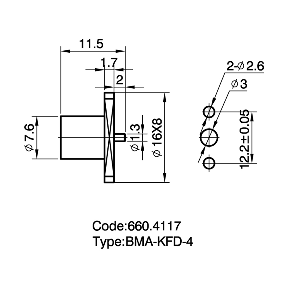
Micro-strip RF Connectors BMA are designed for direct connection between PCB microstrip transmission lines and external RF systems. These connectors are typically mounted horizontally at the edge of a printed circuit board and are also known as BMA End Launch connectors. They provide a transition interface from planar PCB circuits to coaxial RF paths while maintaining signal integrity and mechanical stability.
The main function of Micro-strip RF Connectors BMA is to achieve efficient RF signal conversion between board-level circuits and external coaxial connections. Through optimized contact structures and impedance matching design, these connectors help reduce signal reflection and discontinuity during the transition from microstrip lines to coaxial transmission structures.
Yangzhou Jingcheng Electronics Co., Ltd. is a China Micro-strip RF Connectors BMA Manufacturer and Supplier specializing in the research, development, and manufacturing of RF coaxial connectors, cable assemblies, and passive microwave components. The company follows international standards including MIL, IEC, and GB, with ISO9001 certification and a product range covering over 30 RF connector series and more than 2,000 specifications.
Structural Features of Micro-strip RF Connectors BMA
Micro-strip BMA connectors combine BMA blind-mate technology with PCB edge launch mounting structures. They are commonly installed at the PCB edge, allowing the RF signal from a microstrip transmission line to enter a coaxial connector interface without requiring additional vertical space above the circuit board.
- End Launch PCB mounting: The horizontal edge-mounted design provides a compact RF transition solution and minimizes vertical installation requirements.
- Low-profile structure: The connector occupies limited PCB space, making it suitable for stacked boards and high-density electronic assemblies.
- Impedance matching optimization: The contact pin and ground structure are designed to reduce discontinuities between PCB microstrip lines and coaxial transmission paths.
- Self-guiding alignment: The front interface includes a lead-in chamfer structure to support smoother blind-mate connections.
- PCB material compatibility: The design can be optimized for common RF substrates such as Rogers materials and FR-4 circuit boards.
- Stable mechanical connection: The BMA interface provides reliable mating performance for modular RF equipment.
Common Types and Characteristics of Micro-strip BMA RF Connectors
| Type |
Features |
Typical Applications |
| Standard End Launch BMA Connector |
PCB edge mounting structure for direct microstrip-to-coax transition |
RF modules, microwave circuits, communication equipment |
| Low Profile Micro-strip BMA Connector |
Reduced vertical height for compact electronic designs |
Stacked PCB systems and miniaturized devices |
| Blind-Mate Micro-strip BMA Connector |
Floating interface with alignment compensation capability |
Modular RF assemblies and replaceable circuit units |
| Customized PCB BMA Connector |
Customized pin dimensions, mounting structure, and PCB compatibility |
Specialized RF systems and engineering projects |
| High-Frequency Micro-strip Connector |
Optimized for microwave applications with controlled impedance design |
Test systems, aerospace electronics, high-speed RF circuits |
Core Performance Characteristics of Micro-strip RF Connectors BMA
- Efficient RF transition: Provides a controlled transition between PCB microstrip lines and coaxial interfaces.
- Low signal reflection: Optimized impedance matching helps reduce return loss caused by transmission structure changes.
- Space-saving design: The horizontal mounting structure supports compact PCB layouts and multi-layer electronic architectures.
- Blind-mate capability: Allows easier module assembly where direct visual alignment is difficult.
- High-frequency performance: Suitable for RF and microwave applications requiring stable signal transmission.
- PCB compatibility: Supports different PCB materials and circuit design requirements through customized configurations.
Applications of Micro-strip RF Connectors BMA
Micro-strip BMA connectors are used in RF systems where PCB integration, compact installation, and reliable signal transmission are required. Typical application fields include:
- Wireless communication equipment: Used in RF modules, base station components, and signal processing systems.
- Aerospace electronics: Applied in compact microwave systems requiring lightweight and reliable interconnection.
- Radar and microwave systems: Used for PCB-level RF signal routing and module connections.
- RF test equipment: Provides a convenient interface between measurement instruments and circuit boards.
- Automotive electronics: Applied in high-frequency vehicle communication and sensing modules.
- Defense and industrial electronics: Used in modular RF equipment requiring stable performance and compact structure.
Micro-strip BMA Connectors vs Traditional SMA PCB Connectors
| Comparison |
Micro-strip RF Connectors BMA |
SMA PCB Connectors |
| Mounting Method |
Horizontal PCB edge launch mounting |
Usually vertical or fixed threaded mounting |
| Connection Type |
Blind-mate BMA interface |
Threaded SMA interface |
| Space Requirement |
Suitable for low-profile and stacked PCB designs |
Requires more mechanical clearance |
| Alignment Capability |
Provides self-guiding alignment during mating |
Requires manual alignment during connection |
Compared with traditional SMA PCB connectors, Micro-strip BMA connectors are more suitable for modular RF systems requiring compact PCB integration and blind-mate connection. SMA connectors are commonly selected for applications where threaded locking and frequent manual connection are preferred.
How to Select the Right Micro-strip RF Connector BMA?
The selection of a suitable Micro-strip RF Connector BMA requires consideration of PCB design, electrical performance, mechanical structure, and application environment.
- PCB material: Confirm compatibility with PCB substrates such as Rogers, FR-4, or other RF laminates.
- Frequency range: Select connector models according to the operating frequency requirements of the RF system.
- PCB thickness: Ensure the connector mounting structure matches the circuit board thickness.
- Signal routing design: Evaluate microstrip line width, impedance requirements, and transition structure.
- Installation space: Consider whether a low-profile or standard structure is required.
- Mating requirements: Choose BMA blind-mate designs when modular insertion and repeated assembly are required.
FAQ About Micro-strip RF Connectors BMA
What is a Micro-strip BMA RF connector used for?
A Micro-strip BMA RF connector is used to connect PCB microstrip transmission lines with external coaxial RF systems. It provides a transition point between board-level circuits and cable-based RF connections.
Why are BMA End Launch connectors used on PCB edges?
PCB edge mounting allows the connector to directly align with the microstrip signal path while reducing additional space requirements. This structure is suitable for compact RF modules and stacked circuit designs.
Can Micro-strip BMA connectors support high-frequency applications?
Yes. These connectors are designed for RF and microwave systems. Proper impedance matching between the PCB trace and coaxial interface helps maintain signal quality at high frequencies.
What PCB materials can be used with Micro-strip BMA connectors?
Micro-strip BMA connectors can be designed for various PCB materials, including common FR-4 boards and high-frequency Rogers substrates. Selection depends on frequency requirements and circuit design parameters.
Can Yangzhou Jingcheng Electronics provide customized Micro-strip BMA connectors?
Yes. Yangzhou Jingcheng Electronics Co., Ltd. provides RF connector customization services, including connector structure, PCB interface design, cable assemblies, and application-specific RF interconnection solutions.


 English
 中文简体
中文简体