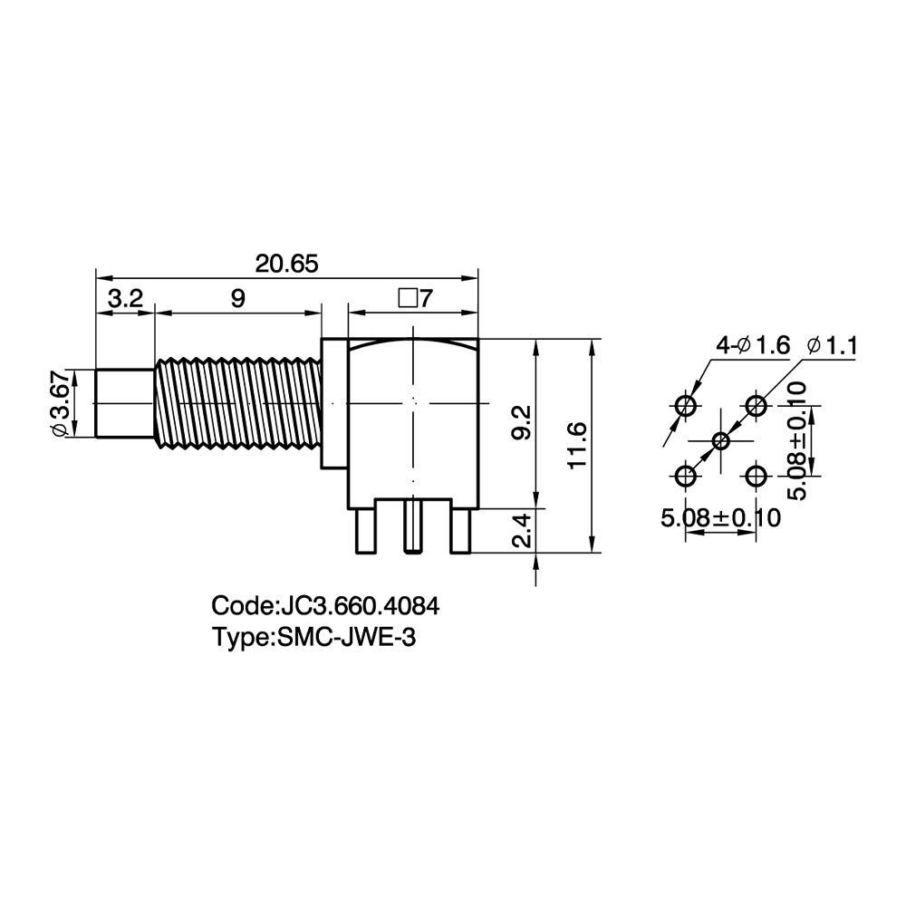
SMC PCB Mount RF Coaxial Connectors Custom

Home / Products / Coaxial Connectors / SMC RF Coaxial Connectors / SMC PCB Mount RF Coaxial Connectors

SMC PCB Mount RF Coaxial Connectors Manufacturer

Product Introduction:
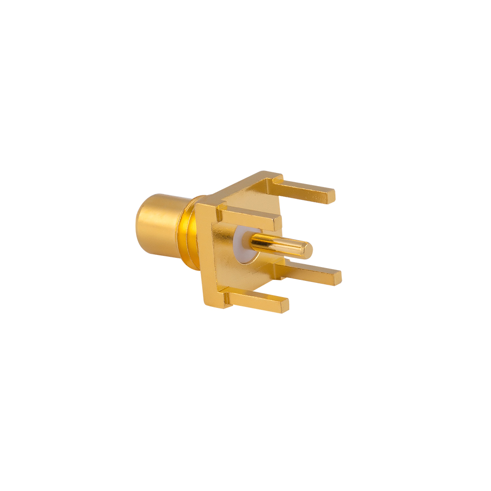
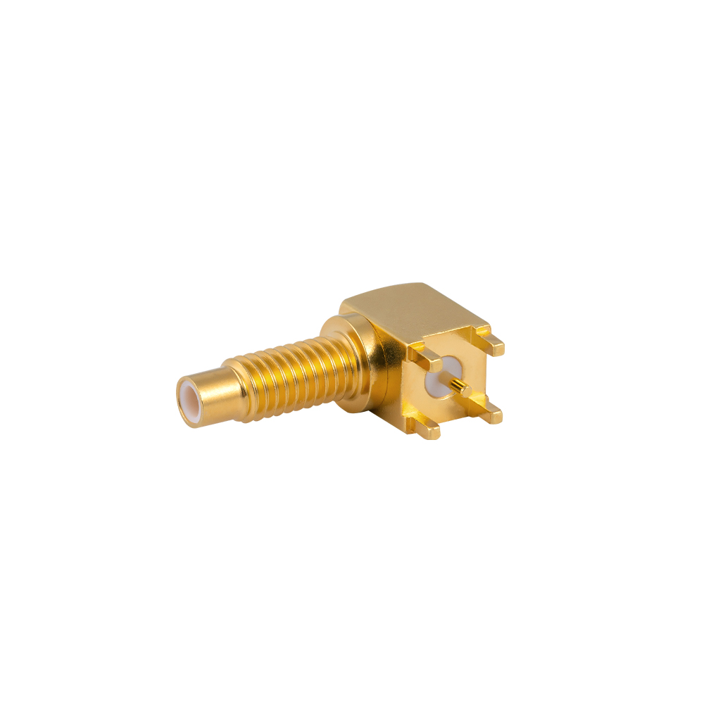
This series includes straight, right-angle, and SMT SMC PCB connectors suitable for automated assembly. It provides a standard threaded external interface for high-frequency signals on PCBs.

Product Features:
High-density routing: Smaller in size compared to SMA connectors, enabling higher port density on the PCB.
Reflow-resistant design: Uses high-temperature PTFE (polytetrafluoroethylene) insulator to ensure dimensional stability during automated soldering processes.
Excellent impedance matching: Optimized transition between pins and pads achieves a Voltage Standing Wave Ratio (VSWR) as low as 1.30 at 3 GHz.

Application Advantages:
Long-term connection reliability: Compared to SMB interfaces, SMC PCB connectors experience less stress on solder pads under lateral cable forces, resulting in longer service life.
Wide industry applicability: Widely used in measurement and control instruments, wireless telemetry, and microwave subsystem modules.

Temperature  Range

-55~+155℃(PE Cable   -40~+85℃)

Impedance

50Ω

Frequency Range

DC~6GHz

Insulation resistance

≥5000MΩ

 Insertion loss

 ≤0.24 dB/6GHz

Voltage Standing Wave Ratio (VSWR)

 Straight ≤1.30/3GHz


 Right  angle ≤1.45/3GHz

 Durability(mating)

≥500 cycles

About
Yangzhou Jingcheng Electronics Co., Ltd.

Yangzhou Jingcheng Electronics Co., Ltd., a premier China SMC PCB Mount RF Coaxial Connectors Manufacturer and SMC PCB Mount RF Coaxial Connectors Supplier, was founded in 1999. It is a high-tech enterprise specializing in the R&D and manufacturing of RF coaxial connectors, cable assemblies, and passive microwave components.
Equipped with a comprehensive R&D and production system, the company has obtained international certifications including ISO9001. Adhering strictly to standards such as MIL, IEC and GB, we offer over 30 product series with more than 2,000 specifications, covering SMA, BNC, N-type and other mainstream models. Our products are widely applied in the fields of communications, aerospace, automotive electronics and beyond, and exported to many countries and regions across Europe, America and Asia.
We uphold the tenet of "Quality as the Foundation, Customers as the Core", committed to providing reliable interconnection solutions and professional services for global clients.

SMC PCB Mount RF Coaxial Connectors Industry knowledge
RF Interconnect Series

SMC PCB Mount RF Coaxial Connectors

SMC PCB Mount RF Coaxial Connectors are subminiature, threaded-coupling interconnects built for board-level RF and microwave signal transfer in space-constrained assemblies. The screw-coupling interface provides a mechanically locked, vibration-resistant mating condition, while controlled impedance geometry maintains signal integrity from DC up into the microwave range, depending on connector design and dielectric material.

Core Function and Performance

This connector category is engineered to join coaxial cable or internal RF circuitry directly to a printed circuit board, forming a compact transition point between a board-level signal path and an external cable assembly or module interface. The threaded coupling nut distinguishes this category from snap-on subminiature types, giving it a defined mating torque, resistance to accidental disconnection, and repeatable return loss performance across multiple mating cycles.

Coupling Mechanism

Threaded (screw-type) coupling nut, distinct from snap-on MCX/MMCX interfaces, reducing risk of unintentional disconnection under vibration.

Impedance Control

Standard characteristic impedance of 50 ohms, supporting consistent VSWR and return loss across the rated frequency band.

Mounting Footprint

Compact subminiature body size relative to SMA, allowing tighter board layout and reduced spacing between adjacent RF ports.

Board Interface Options

Through-hole, surface mount (SMT), edge launch, and right-angle configurations to match different board thicknesses and layout constraints.

Contact Plating

Gold-plated center contact and nickel- or gold-plated shell options, addressing conductivity and mating-cycle durability requirements.

Frequency Coverage

Typical operating range from DC to several GHz, with specific upper limits determined by dielectric material and connector geometry.

Common Types and Characteristics

Within the broader category, SMC connectors are differentiated primarily by mounting orientation, board interface method, and gender. The table below summarizes the configurations most frequently specified for PCB-level integration.

Type Mounting Style Gender Typical Use
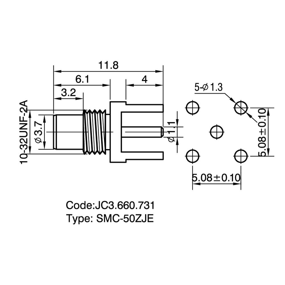
Straight PCB Mount (Through-Hole) Vertical, pins soldered through board Jack / Plug Standard vertical board-to-cable transition
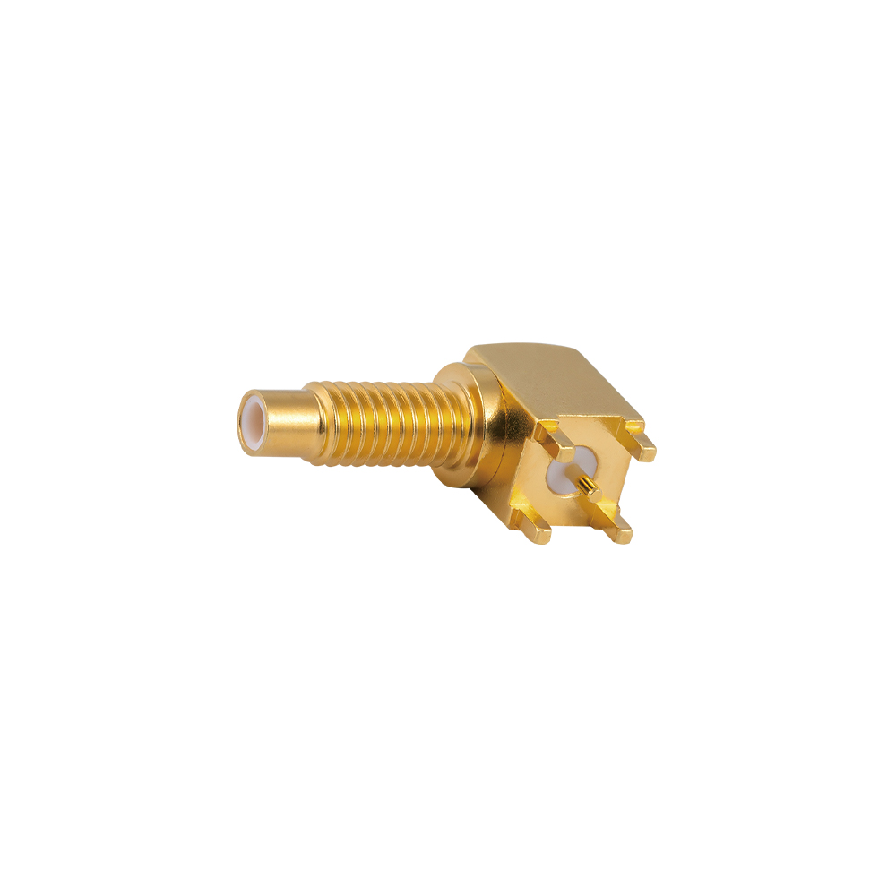
Right Angle PCB Mount 90° orientation, low-profile Jack / Plug Height-restricted enclosures, side-panel routing
Edge Launch / Edge Mount Mounted along board edge, aligned with trace Jack High-frequency signal launch with minimized discontinuity
Surface Mount (SMT) Reflow-solderable footprint, no drilled holes Jack / Plug Automated assembly lines, high-density boards
Bulkhead / Panel Mount Front-panel mounted with rear PCB pin Jack Chassis-level RF ports needing external cable access

Application Scenarios

  • Telecommunication base station modules and RF front-end boards
  • Test and measurement instruments requiring stable board-level RF ports
  • GPS/GNSS receiver modules and navigation equipment
  • Aerospace and defense electronics with vibration exposure
  • Industrial RF and wireless communication modules
  • Medical electronic equipment with internal RF signal routing
  • Antenna feed circuits and signal distribution boards
  • Compact RF assemblies where snap-on connectors do not meet coupling retention needs

Selection Points

  • Frequency range: Confirm the connector's rated upper frequency covers the signal band used on the board.
  • Mounting method: Match through-hole, SMT, edge launch, or right-angle style to the available board thickness and layout.
  • Impedance matching: Verify 50-ohm impedance consistency with the connected cable assembly or trace design to control VSWR.
  • Mating cycle rating: Consider expected connect/disconnect frequency during production testing or field service.
  • Plating and materials: Select gold or nickel plating based on conductivity, corrosion resistance, and cost requirements.
  • Gender and interface compatibility: Confirm mating compatibility with the corresponding cable-side or panel-side connector.
  • Environmental exposure: Account for humidity, temperature range, and vibration where the assembly will operate.

Comparison with Related Subminiature Series

SMC is frequently compared with other subminiature RF connector families used in board-level and compact cable assemblies. The comparison below outlines the primary distinctions relevant to selection.

Series Coupling Type Relative Size Typical Frequency Range Coupling Retention
SMC Threaded (screw-on) Subminiature DC to several GHz High, resistant to vibration
SMA Threaded (screw-on) Standard subminiature (larger than SMC) DC to 18/26.5 GHz High
MCX Snap-on Smaller than SMC DC to 6 GHz Moderate, quick connect/disconnect
MMCX Snap-on, micro-miniature Smaller than MCX DC to 6 GHz Moderate

Frequently Asked Questions

What distinguishes SMC connectors from SMA connectors?

Both use a threaded coupling nut, but SMC connectors are built to a smaller subminiature footprint, allowing tighter board spacing, while SMA connectors are physically larger and rated for wider frequency ranges in many designs.

Can SMC PCB mount connectors be used with automated SMT assembly lines?

Surface mount (SMT) variants within this category are designed with reflow-solderable footprints, making them compatible with automated pick-and-place and reflow soldering processes.

How is mating cycle life determined for this connector type?

Mating cycle life depends on contact plating, spring contact design, and coupling nut material, and is typically validated through repeated connect/disconnect testing under controlled torque conditions.

Does board thickness affect connector selection?

Board thickness affects pin length requirements for through-hole types and clearance for right-angle or edge launch types, so this dimension should be confirmed before specifying a mounting style.

Are custom specifications available beyond standard catalog dimensions?

Custom pin length, plating, flange dimensions, and impedance tuning are commonly available on request when standard catalog parts do not match a specific board layout.

Yangzhou Jingcheng Electronics Co., Ltd. designs and manufactures SMC PCB Mount RF Coaxial Connectors alongside related SMA, MCX, MMCX, and adapter series, supported by in-house CNC machining and network analyzer testing for impedance consistency across production batches. Products are produced under ISO9001 and ISO14001 management systems, with design and inspection referencing GB, MIL-C, and IEC standards.