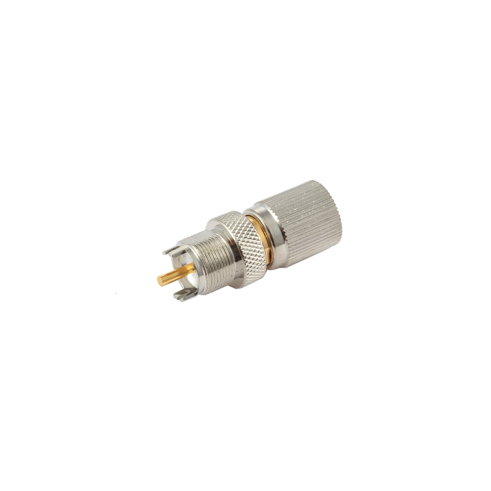
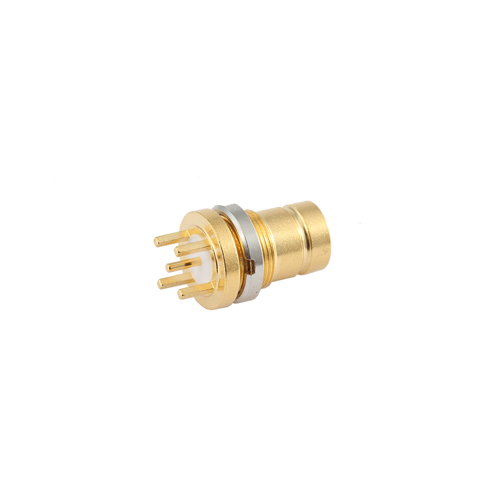
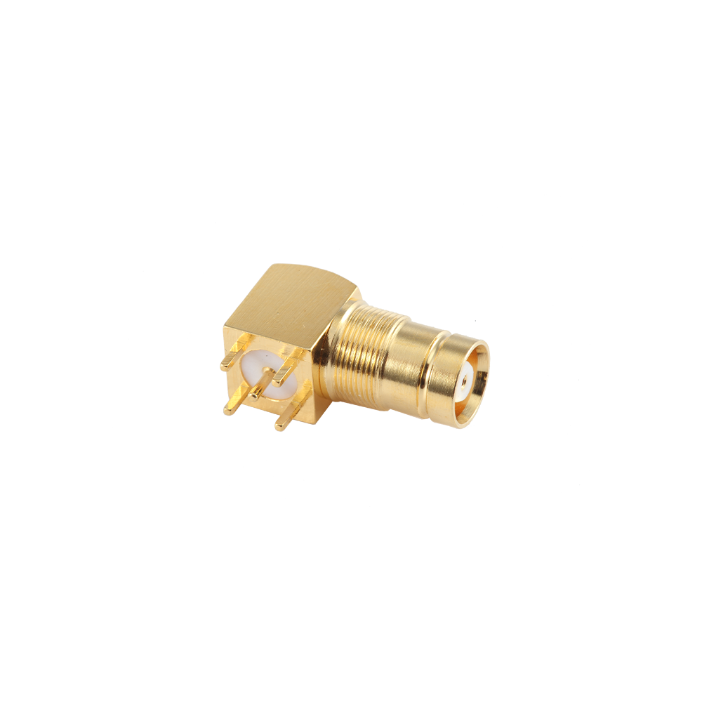
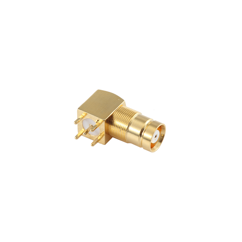
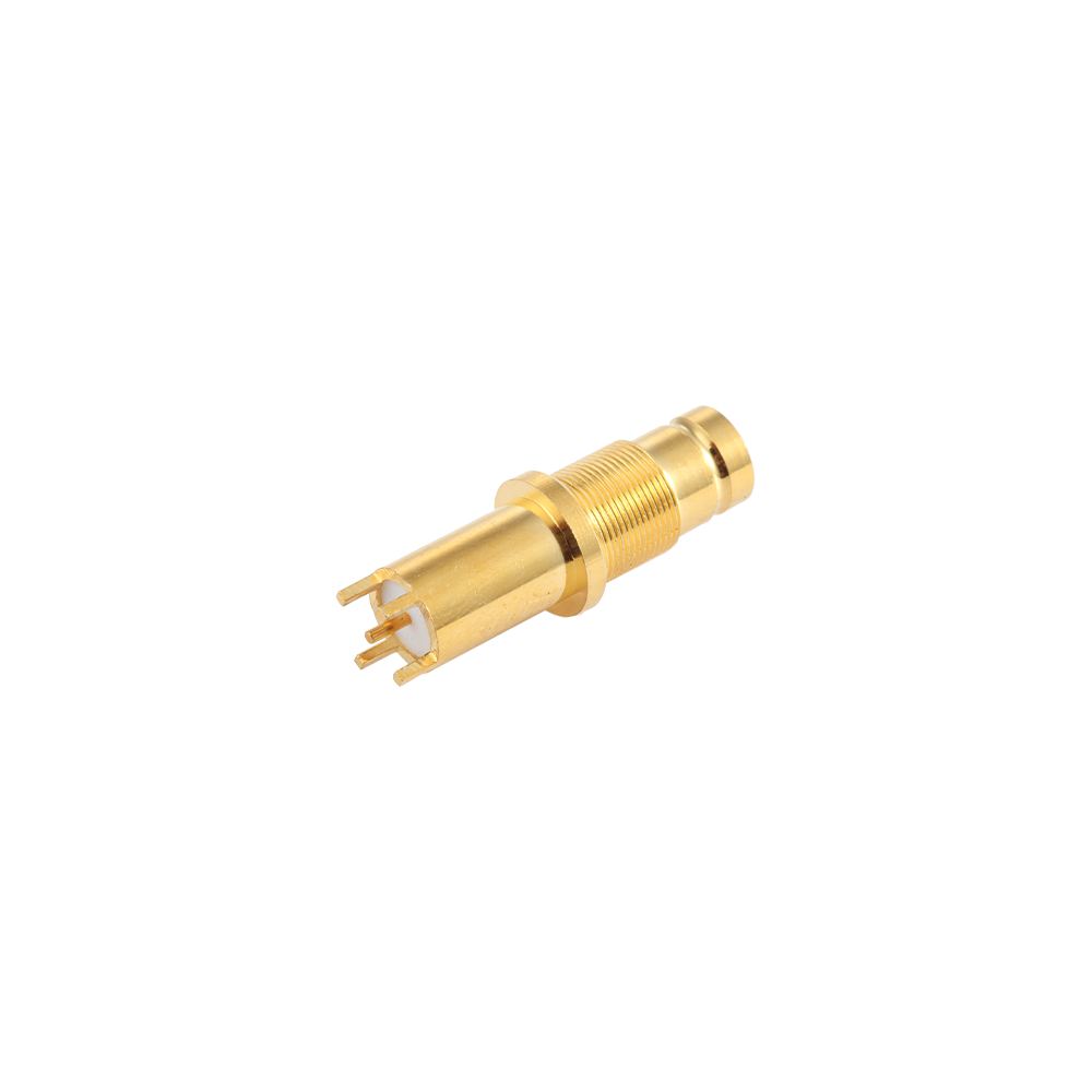
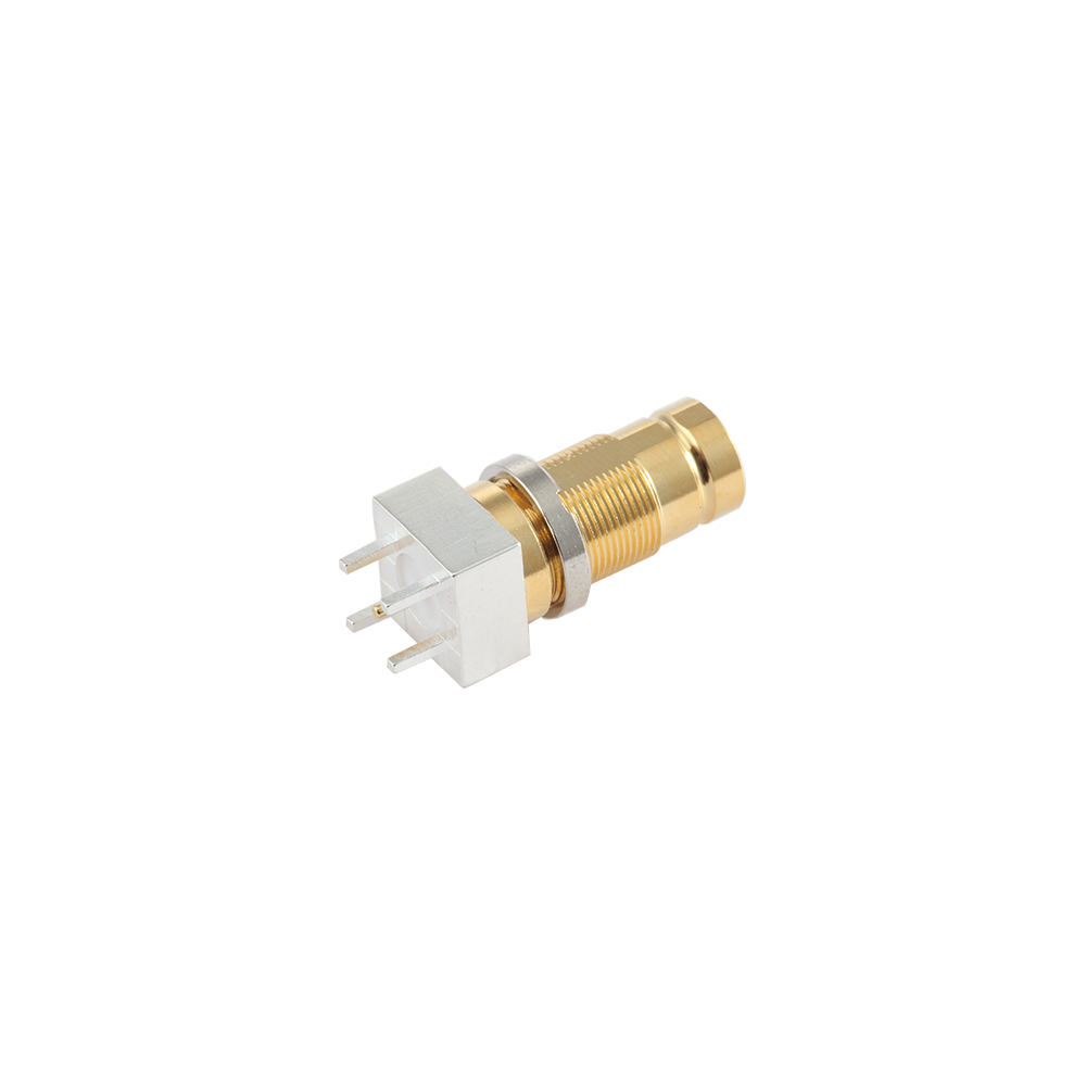
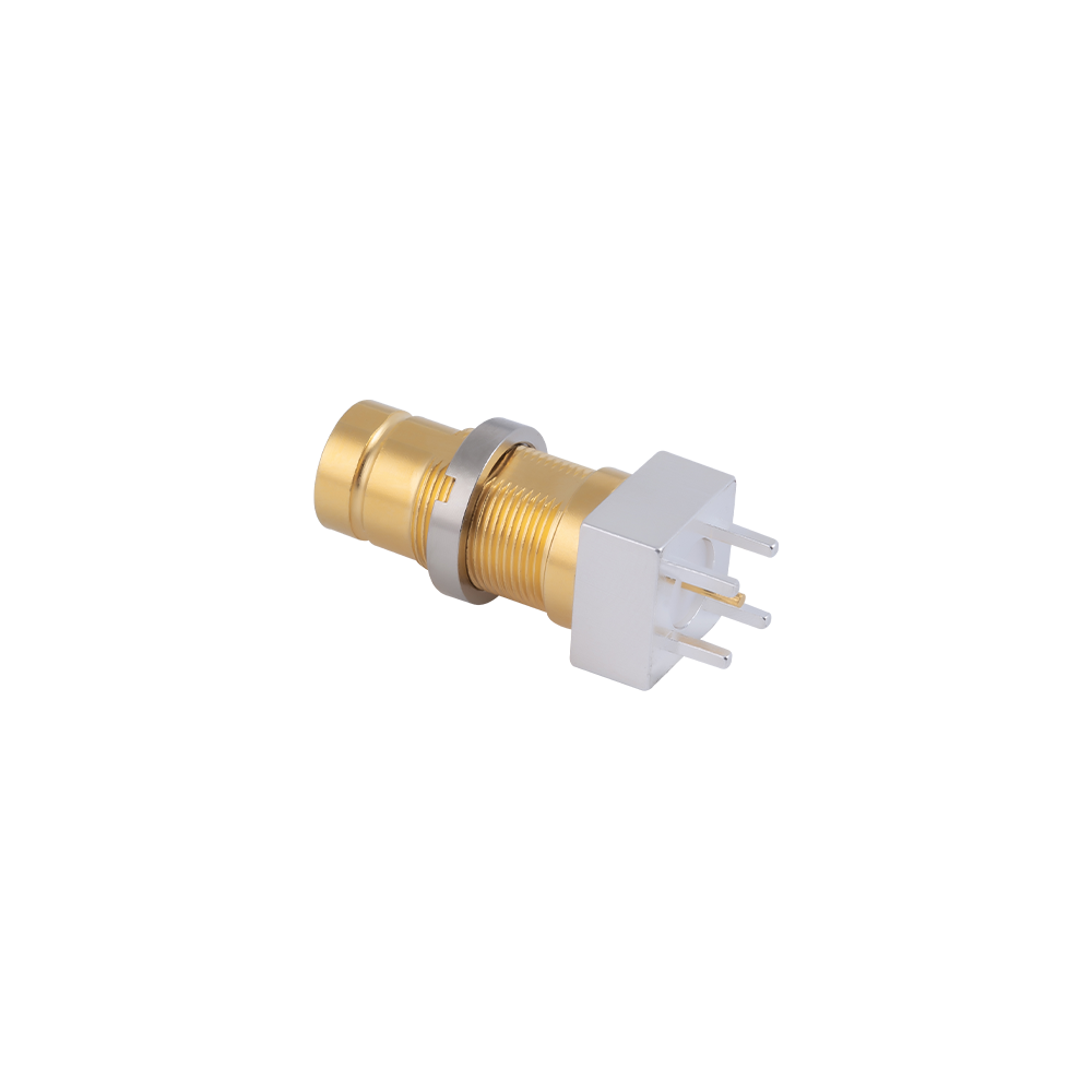
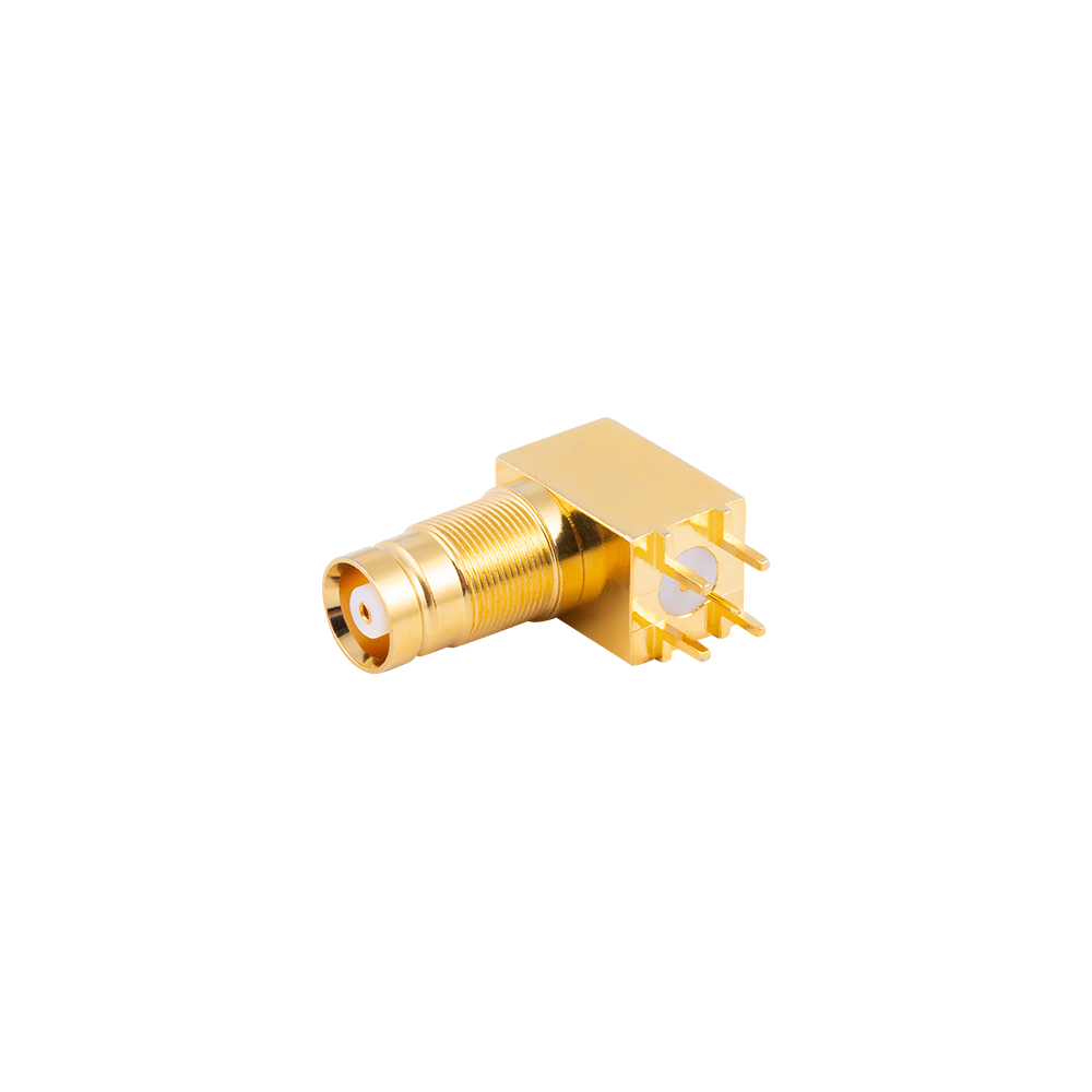
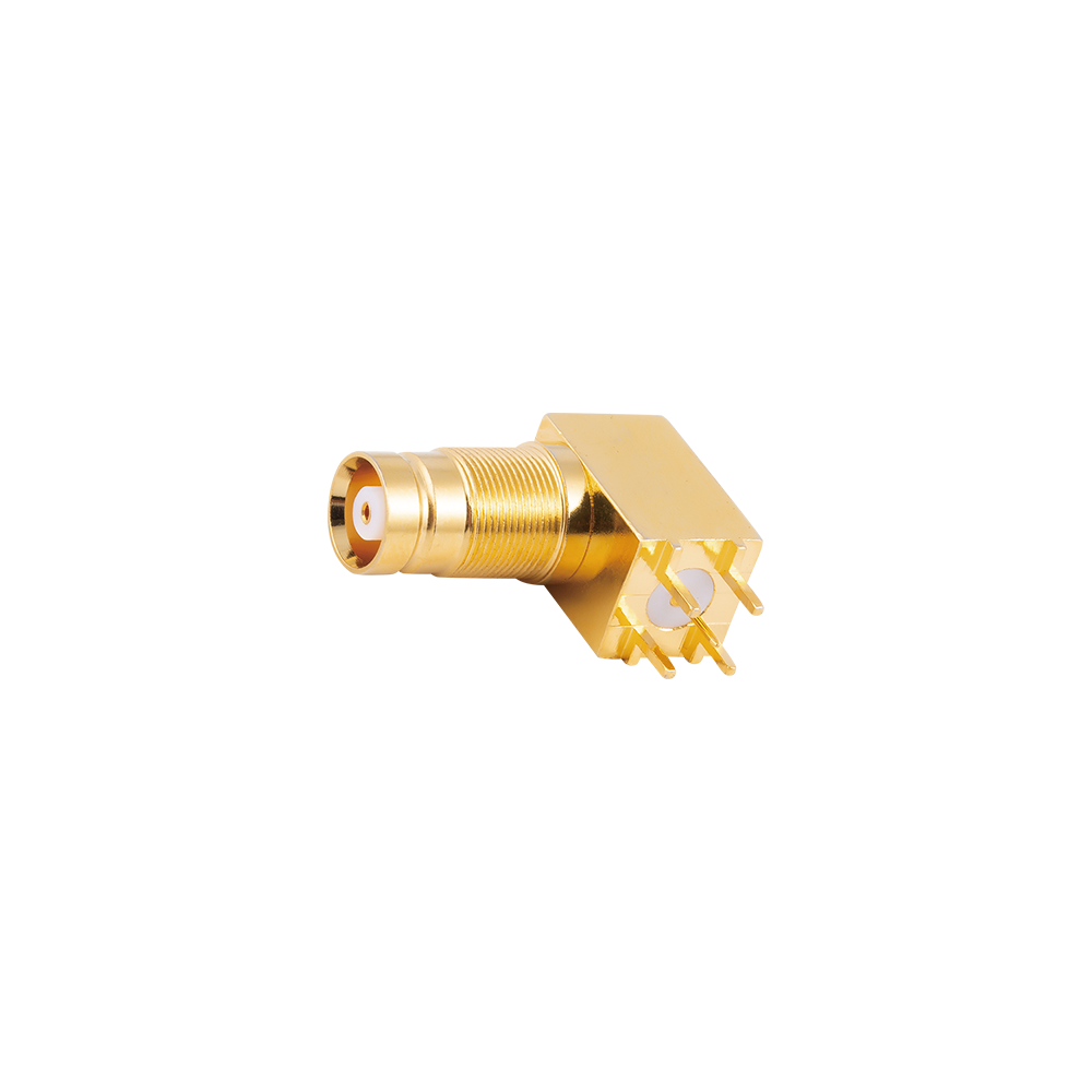
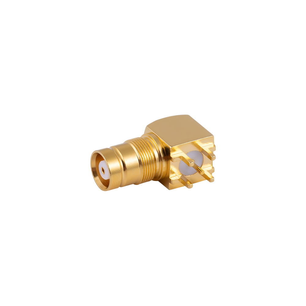
1.6/5.6 (L9) PCB Connectors are compact RF coaxial connectors designed for direct mounting onto printed circuit boards, providing a fixed interface between the board-level circuit and external coaxial cable. Built on the 1.6/5.6 DIN interface standard, this connector series maintains stable 75Ω impedance and is engineered for space-constrained board layouts commonly found in video processing modules, CCTV equipment, and telecommunication transmission circuits. 1.6/5.6 (L9) PCB Connectors are typically soldered directly onto the board through-hole or surface pads, forming a mechanically fixed and electrically stable connection point for signal input or output.
Compared with cable-mount or panel-mount connectors, 1.6/5.6 (L9) PCB Connectors integrate directly into the board assembly process, eliminating the need for a separate cable segment between the board and the connector interface. This mounting method reduces signal path length and associated insertion loss, which is beneficial in compact video and RF circuit designs where board space and signal integrity are both important considerations. Contact components in this category are typically machined from brass or phosphor bronze and finished with gold or nickel plating to meet solderability and conductivity requirements.
Common Types and Characteristics
| Type |
Mounting Style |
Gender |
Typical Impedance |
Key Characteristics |
| 1.6/5.6 Straight PCB Jack |
Through-hole board mount |
Female |
75Ω |
Vertical mounting for standard board layouts |
| 1.6/5.6 Right Angle PCB Jack |
Through-hole board mount |
Female |
75Ω |
Horizontal cable exit for low-profile enclosures |
| 1.6/5.6 SMT PCB Connector |
Surface mount |
Female |
75Ω |
Suited for automated pick-and-place assembly |
| 1.6/5.6 PCB Connector with Flange |
Board mount with panel fixation |
Female |
75Ω |
Combines board connection with mechanical panel support |
Application Scenarios and Selection Points
1.6/5.6 (L9) PCB Connectors are applied in CCTV camera modules, video distribution boards, telecommunication transmission circuits, and other compact RF or video circuits where a direct board-level coaxial interface is required. When selecting a connector from this category, the following points are recommended for confirmation:
- Mounting orientation — straight or right-angle, based on the board layout and enclosure height
- Mounting method — through-hole or surface mount, matched to the board assembly process
- Impedance matching — 75Ω configuration confirmed against the video or data transmission system requirements
- Plating material — gold plating for improved solderability and conductivity, nickel plating for general durability
- Mechanical fixation requirement — flange-type PCB connectors recommended where additional panel support is needed
PCB Connectors vs. Cable Mount Connectors
| Connector Type |
Interface |
Signal Path |
Typical Application |
| PCB Connector |
Direct board solder connection |
Short, board-level |
Video modules, compact RF circuit boards |
| Cable Mount Connector |
Cable termination |
Extended, via cable assembly |
Jumper leads, patch cables, panel interconnects |
FAQ
Q: What mounting methods are available for 1.6/5.6 (L9) PCB Connectors?
A: This category includes through-hole mounting for standard board layouts and surface mount versions suited for automated assembly processes.
Q: What is the typical impedance of these connectors?
A: 1.6/5.6 (L9) PCB Connectors are typically configured for 75Ω impedance, matching common video and CATV transmission standards.
Q: Can PCB connectors include additional panel fixation?
A: Flange-type PCB connectors are available to provide both a board-level solder connection and mechanical support against an equipment panel.
Q: Are pad or through-hole dimensions customizable?
A: Mounting footprint and pin dimensions can be adjusted according to customer PCB layout and drawings.
1.6/5.6 (L9) PCB Connectors in this category are manufactured by Yangzhou Jingcheng Electronics Co., Ltd., a company specializing in RF coaxial connector design and production since 1999, with in-house manufacturing and high precision testing equipment supporting consistent electrical performance across board-mounted RF interfaces.


 English
 中文简体
中文简体