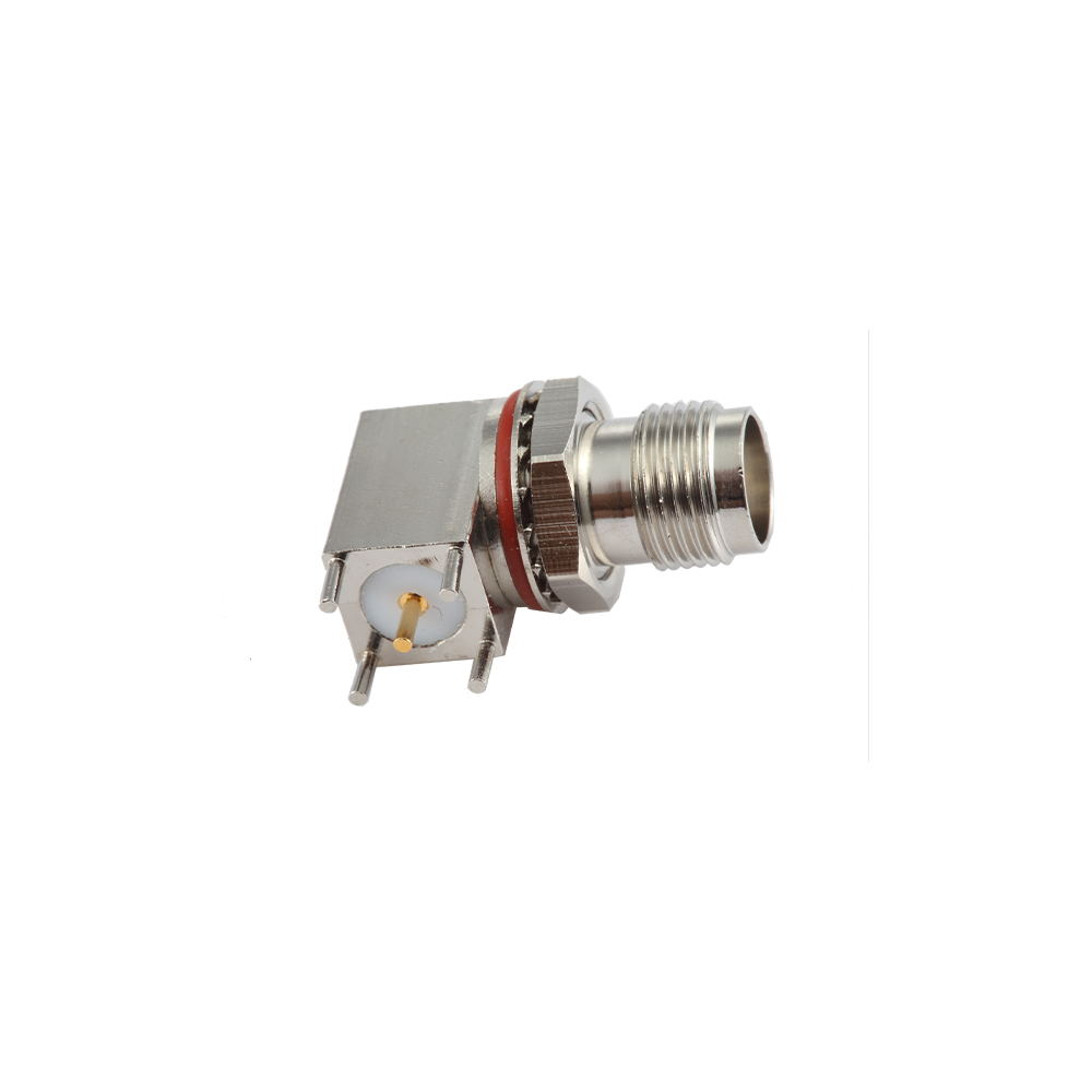
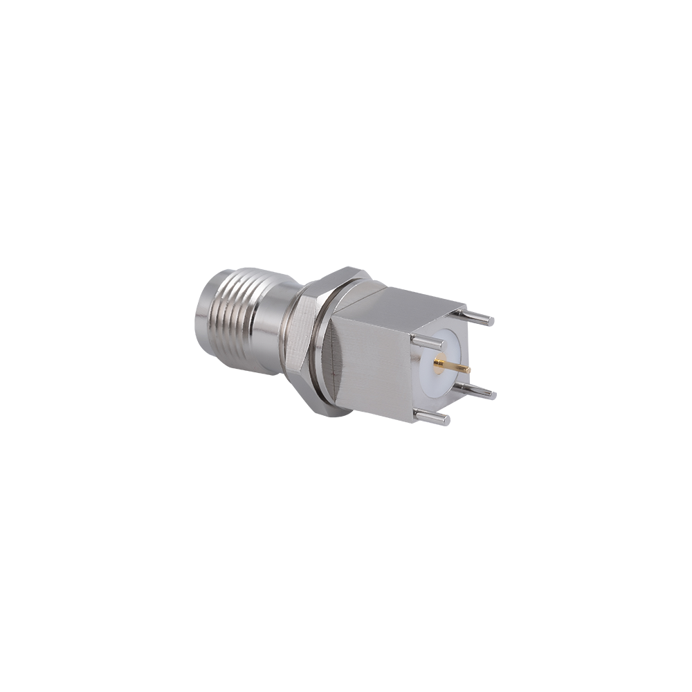
TNC PCB Connectors Custom

Home / Products / Coaxial Connectors / TNC RF Coaxial Connectors / TNC PCB Connectors

TNC PCB Connectors Manufacturer

Product Overview

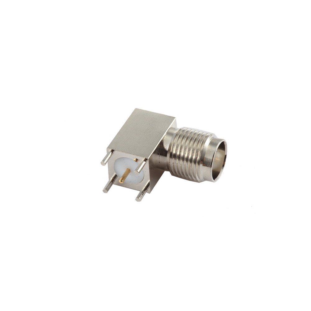
TNC PCB Connectors mount directly to a printed circuit board—either through-hole soldered or surface-mount reflow—eliminating the pigtail cable between board and panel connector that adds cost, insertion loss, and a potential failure point to every RF signal path exiting the board. This direct board integration is the cleanest solution from a signal-integrity standpoint: the RF path transitions from microstrip or stripline on the PCB directly into the TNC connector interface without an intermediate cable transition.

TNC PCB connectors are chosen over SMA PCB connectors—the dominant alternative for 50Ω board-edge RF interfaces—when the application requires the TNC's threaded coupling security in a PCB-mount form factor. This scenario arises in military avionics line-replaceable units (LRUs), vehicle-mounted radio PCBs, and shipborne equipment boards where vibration would work a push-on or bayonet-coupled board connector loose over time. The threaded TNC interface locks the mating cable assembly to the board-mounted connector with measurable, repeatable torque.

Key Features
Through-hole solder mount and surface-mount (SMT, reflow-compatible) footprint options; through-hole versions provide greater mechanical robustness for high-vibration PCB environments.
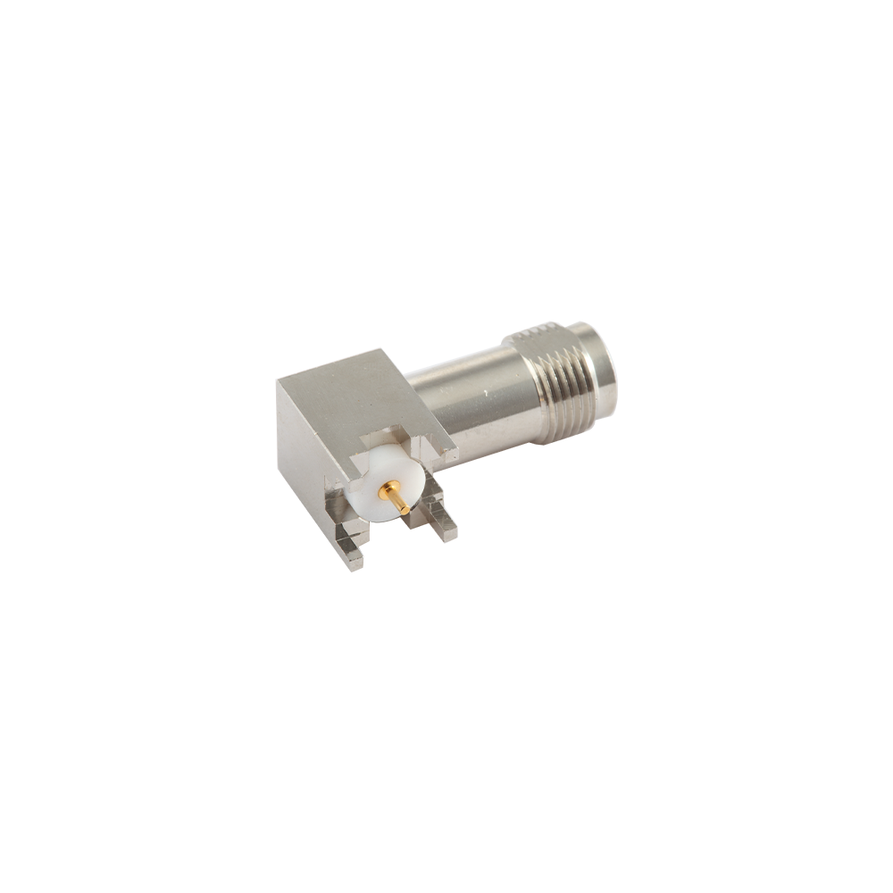
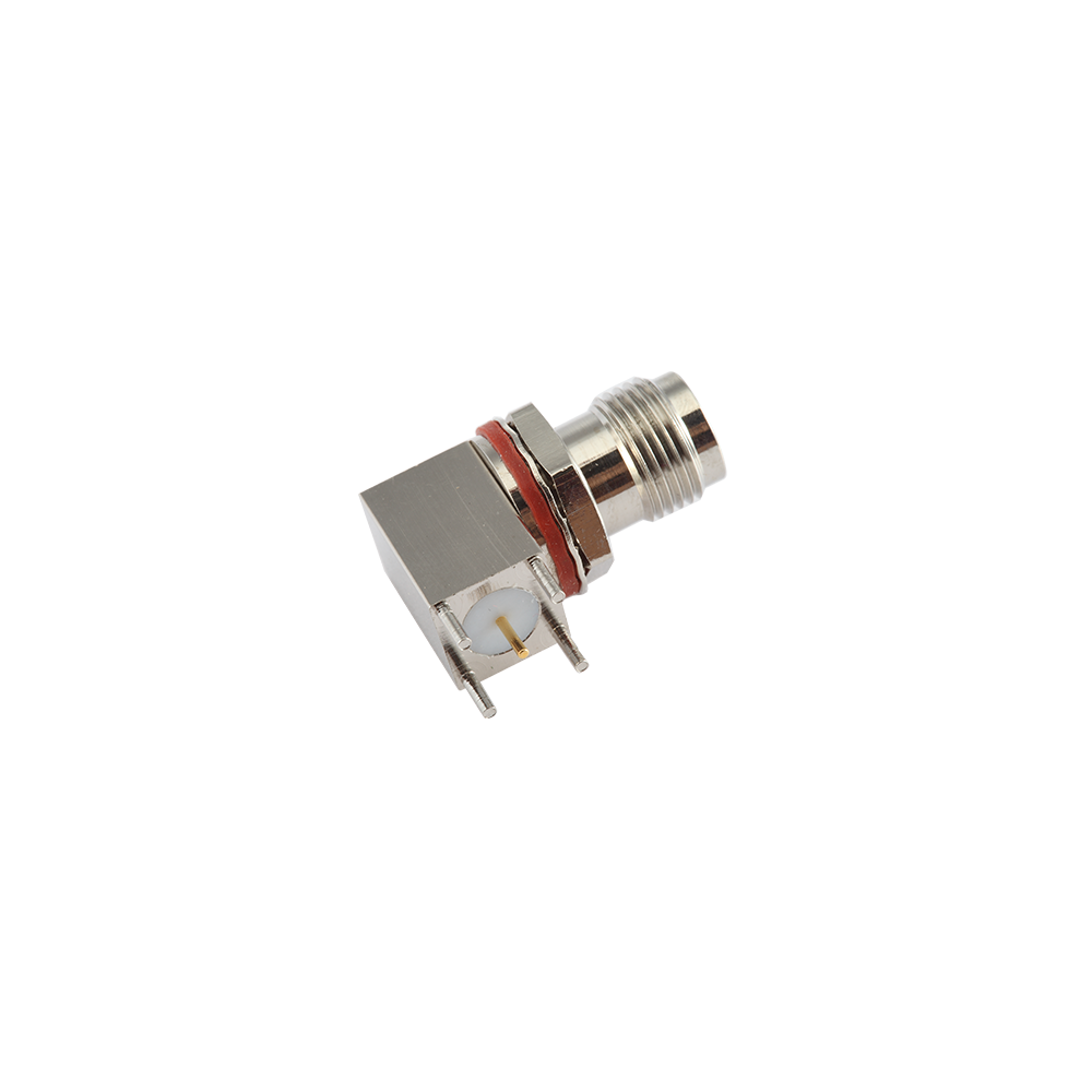
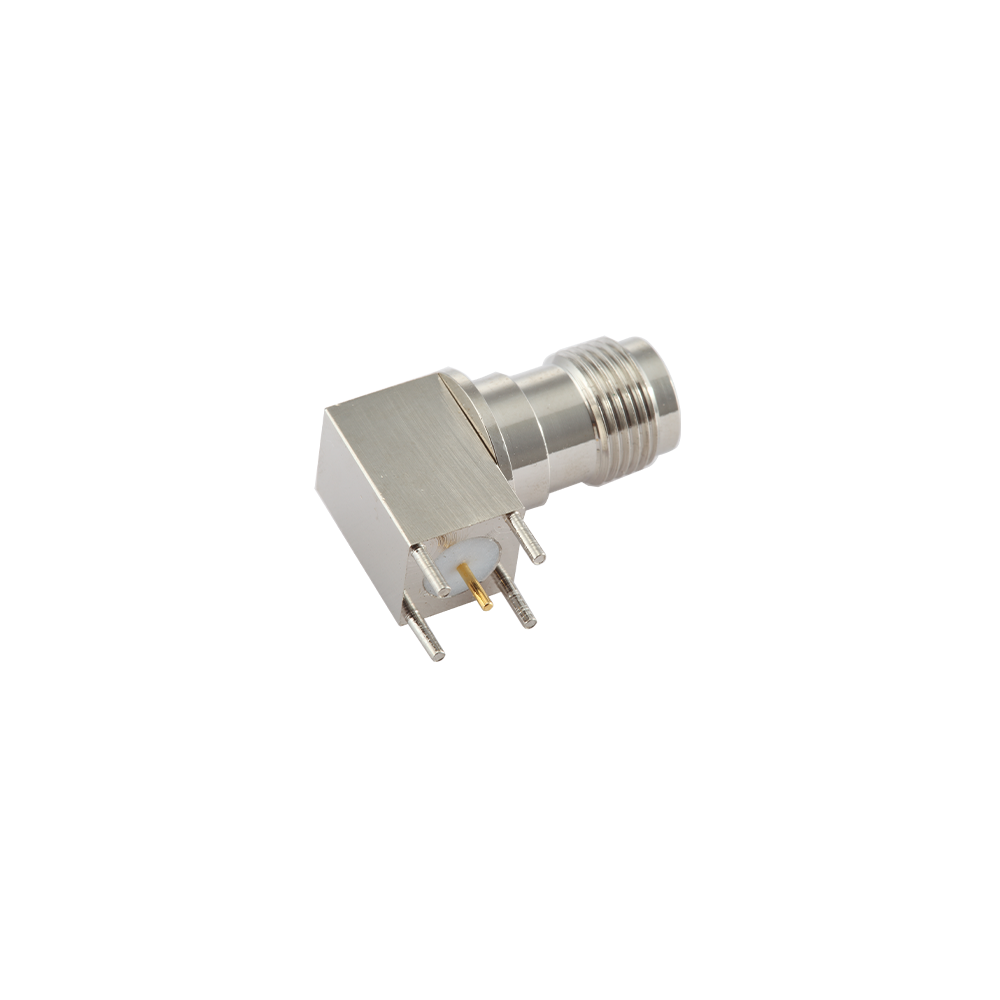
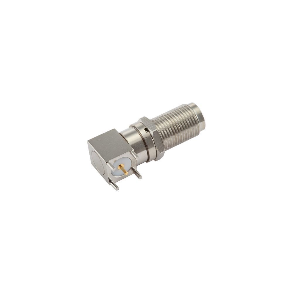
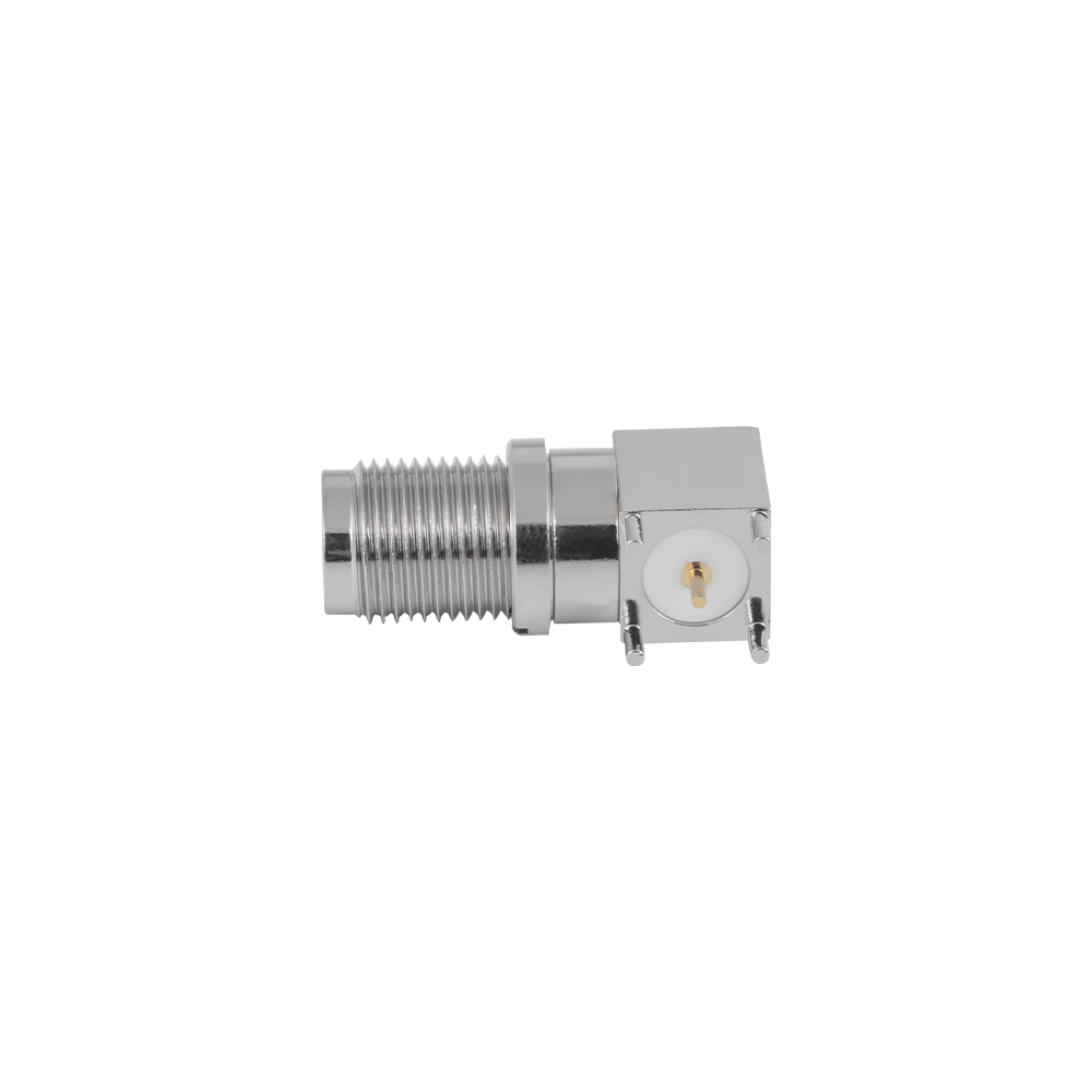
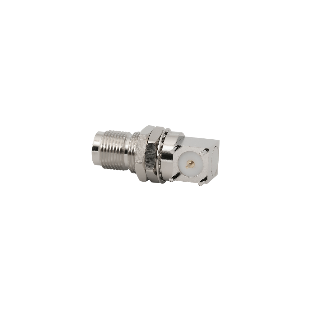
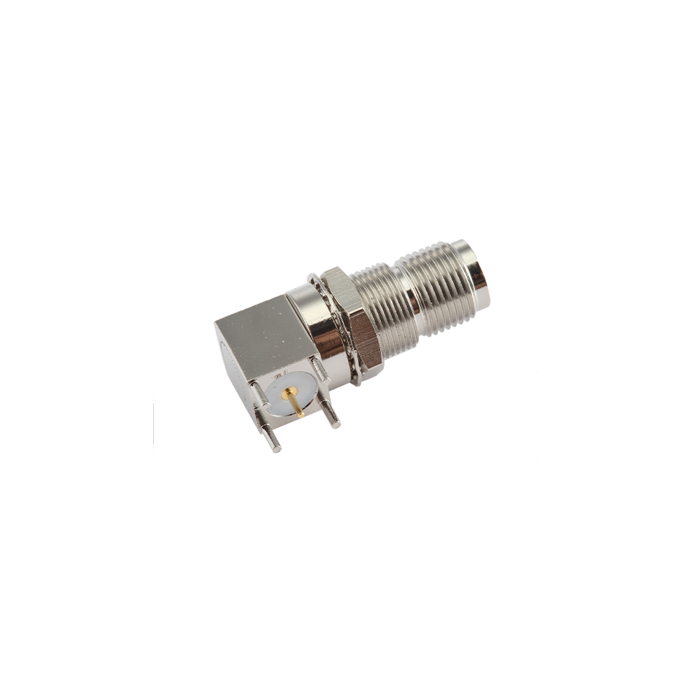
Right-angle (edge-launch / horizontal) and vertical (top-launch / upright) orientations; right-angle versions align with the PCB edge for panel-exit cable connections, vertical versions accept a perpendicular mating cable.
Controlled impedance center pin and dielectric geometry ensures 50Ω launch transition from PCB trace to connector, preserving signal integrity for designs operating to 11 GHz.
PCB land pattern dimensions compliant with IEC 169-16 and consistent with common EDA library standards; STEP 3D models available for PCB mechanical design integration.
Additional solder tail anchoring pins or screw-mount flanges available on selected versions to reinforce the solder joint against cable pull-out forces—important when the PCB connector also serves as the mechanical cable strain relief.
Lead-free, RoHS-compliant solder terminations; compatible with standard IPC J-STD-001 lead-free assembly processes and peak reflow temperatures to 260°C.

Competitive Advantages
Jingcheng's engineering team can provide RF board-launch consultation as part of the design-in process: reviewing PCB stackup, trace geometry, and via structures at the connector transition to identify and resolve impedance mismatch before board fabrication. This reduces the number of PCB re-spins required to meet RF performance targets—a meaningful cost saving on complex multi-layer RF boards.
STEP 3D models and Gerber-compatible land pattern data are available for standard catalogue variants, integrating seamlessly into customer PCB layout workflows without additional mechanical drawing translation work.
SMT reel packaging is available for high-volume PCB assembly line consumption. Tape-and-reel component orientation and pocket dimensions are documented in the packaging specification, simplifying SMT machine programming.
Jingcheng's 25+ years of TNC connector manufacturing means PCB-mount variant tooling is mature and stable—board designers can rely on dimensional consistency between NPI samples and volume production components, avoiding the process-control issues that can arise with newer suppliers.

Typical Applications
Military avionics LRU RF interface boards requiring locked cable connections under vibration
Vehicle-mounted radio and tactical communication module PCBs
Shipborne radar signal processor and receiver front-end boards
Microwave transceiver modules for wireless infrastructure equipment
Industrial wireless sensor nodes and condition monitoring systems operating in the microwave spectrum
RF test fixture boards and calibration standard assemblies

FAQ
Q: What PCB thickness is supported for through-hole TNC PCB connectors?
A: Standard solder tail lengths target 1.6 mm PCB thickness. Extended tail lengths for 2.4 mm and 3.2 mm boards are available as configured variants. Specify the PCB thickness and layer count in your inquiry; the engineering team will confirm the appropriate tail geometry.
Q: Can TNC PCB connectors be used in a conformal-coated assembly?
A: Yes. Standard TNC PCB connectors are compatible with selective conformal coating processes where the coating is masked from the RF interface mating surfaces. Full-immersion coating is not recommended as it can compromise the mating thread and center contact. Please consult with your conformal coating applicator for masking procedures.
Q: Is there a significant performance difference between right-angle and vertical PCB mount versions?
A: Vertical (upright) versions generally offer slightly better VSWR performance at frequencies above 6 GHz because the signal path through the connector is more linear. Right-angle versions introduce a 90° transmission line bend that creates a minor impedance perturbation, resulting in a slightly elevated VSWR approaching the upper frequency limit. For applications below 6 GHz, both orientations perform equivalently within the product specification.
Q: How does Jingcheng validate PCB connector RF performance at the end of the production process?
A: TNC PCB connectors are subject to dimensional inspection of critical interface features (center pin diameter, dielectric length, outer conductor bore) on every production lot. Statistical sampling of soldered assemblies is measured on Agilent vector network analyzers for insertion loss and VSWR. Full inspection records are retained and available to customers as part of the incoming quality data package.
Q: Are reverse-polarity (RP-TNC) versions available in PCB mount configurations?
A: Yes. RP-TNC PCB mount connectors in both right-angle and vertical orientations are available. RP-TNC PCB connectors are used in WiFi access point and router board designs where the antenna port is required to be RP-TNC per regulatory antenna-locking conventions. Please specify RP when placing your order or sample request.

Temperature Range

-55~+155℃

Impedance

50Ω

Frequency Range

DC~11GHz

Insulation resistance

≥5000MΩ

Insertion loss

≤0.20 dB/1GHz

VSWR

Straight ≤1.22/3GHz

Right angle

≤1.30/3GHz

Durability(mating)

≥500 (cycles)

About
Yangzhou Jingcheng Electronics Co., Ltd.

Yangzhou Jingcheng Electronics Co., Ltd., a premier China TNC PCB Connectors Manufacturer and TNC PCB Connectors Supplier, was founded in 1999. It is a high-tech enterprise specializing in the R&D and manufacturing of RF coaxial connectors, cable assemblies, and passive microwave components.
Equipped with a comprehensive R&D and production system, the company has obtained international certifications including ISO9001. Adhering strictly to standards such as MIL, IEC and GB, we offer over 30 product series with more than 2,000 specifications, covering SMA, BNC, N-type and other mainstream models. Our products are widely applied in the fields of communications, aerospace, automotive electronics and beyond, and exported to many countries and regions across Europe, America and Asia.
We uphold the tenet of "Quality as the Foundation, Customers as the Core", committed to providing reliable interconnection solutions and professional services for global clients.

TNC PCB Connectors Industry knowledge

TNC PCB Connectors mount directly onto a printed circuit board, providing a board-level RF interface that uses the threaded TNC coupling nut at the mating side. Because mating and unmating a threaded TNC interface applies a rotational torque to the connector body, TNC PCB Connectors are generally built with reinforced mounting pins, a mechanical anchor point, or an additional mounting bracket to transfer that torque into the board structure rather than into the solder joints alone. This category of TNC PCB Connectors is used where a circuit board requires a secure, vibration-resistant RF port for test access, module interconnection, or signal input/output at the board level.

Mounting and Core Features

  • Torque-resistant mounting: Additional mounting pins, tabs, or a mechanical bracket help absorb the rotational force applied during cable mating and unmating, reducing stress transferred to the solder joints.
  • Through-hole mounting: Pins pass through drilled holes in the PCB and are wave or hand soldered, providing a mechanically strong board-level joint suited to the threaded mating loads of the TNC interface.
  • Orientation options: Available in vertical (90-degree to the board) and right-angle (edge-mount) configurations depending on the enclosure layout and cable routing direction.
  • Ground pin layout: Multiple ground pins or a ground flange maintain shielding continuity between the connector body and the board ground plane.
  • Board thickness and footprint: Pin length and footprint pattern are matched to a defined PCB thickness range to maintain a consistent mating height and impedance profile.

Common Types and Characteristics

TNC PCB Connectors are generally grouped by mounting orientation and the mechanical reinforcement method used to manage mating torque.

Common types of TNC PCB connectors and their characteristics
Type Mounting Orientation Torque Support Method Typical Use
Vertical Through-Hole 90-degree to board Extra mounting pins around the shell base General test and RF interface boards
Bracket-Reinforced Mount 90-degree to board Metal bracket fixed to the board with screws Boards with frequent cable mating/unmating
Right-Angle Edge Mount Parallel to board edge Extended pin footprint along the board edge Boards with limited vertical clearance
Panel-to-Board Standoff Mount Fixed via standoff, board-connected Standoff post transfers torque to chassis Boards requiring an externally accessible RF port

Application Scenarios

  • Test and measurement circuit boards requiring a secure, threaded RF access point for calibration;
  • Module-to-module RF interconnection within multi-board assemblies subject to vibration;
  • Vehicle-mounted and mobile equipment boards where the front-panel RF port must remain stable under repeated handling;
  • Sensor and data acquisition boards used in industrial monitoring systems with periodic cable connections;
  • Compact instrument designs where a board-mounted TNC port reduces the need for internal cable jumpers.

Selection Guidelines

  1. Mating frequency: For boards where the connector will be mated and unmated frequently, a bracket-reinforced or extra-pin design helps reduce cumulative stress on the solder joints.
  2. Mounting orientation: Determine whether a vertical or right-angle edge-mount configuration is required based on the enclosure layout and available board clearance.
  3. Footprint and pad layout: Confirm the connector's pin spacing and footprint pattern match the PCB layout used in the design.
  4. Board thickness: Verify the connector's pin length and mating height are suitable for the specific PCB thickness used in the assembly.
  5. Grounding and shielding: Check that the ground pin layout and ground flange design provide adequate shielding continuity with the board's ground plane for the intended frequency range.

TNC PCB vs BNC PCB Mounting Comparison

Comparison between TNC and BNC PCB connector mounting considerations
Comparison Item TNC PCB Connector BNC PCB Connector
Mating action on the board Rotational torque from screwing Push and quarter-turn, lower torque
Mechanical reinforcement need Generally higher Generally lower
Solder joint stress risk Higher without added support Lower under normal use
Typical use Boards requiring vibration-resistant RF ports Boards with frequent, quick connect/disconnect use

Frequently Asked Questions

Q1: Why do TNC PCB connectors sometimes include a mounting bracket instead of relying only on solder pins?

Mating and unmating a threaded TNC connector applies a rotational torque to the connector body. A mounting bracket or additional pins help transfer that torque into the board or chassis structure, reducing repeated stress on the solder joints over the life of the assembly.

Q2: What happens if a TNC PCB connector is mounted with solder pins only and no mechanical reinforcement?

Without additional mechanical support, repeated mating and unmating torque can place cumulative stress on the solder joints, which may affect long-term mechanical reliability, particularly in applications where the cable connection is changed frequently.

Q3: Can a TNC PCB connector be replaced after it has been soldered onto a board?

A through-hole mounted TNC PCB connector can generally be desoldered and replaced using standard soldering tools, though care should be taken to avoid damaging surrounding board traces during the rework process.

Q4: How does board thickness affect TNC PCB connector selection?

Connector pin length and standoff height are generally specified for a defined PCB thickness range. Using a board thickness outside this range may affect the mating height and the mechanical fit of the connector on the board.

Manufacturing Note

Yangzhou Jingcheng Electronics Co., Ltd was founded in 1999 and specializes in the design, development, production, and sales of RF coaxial connectors, covering BNC, TNC, N, SMA, 2.92, 2.4, 1.85, and other series, supported by advanced manufacturing equipment and high precision testing equipment. For TNC PCB Connectors, mounting pin dimension control and mechanical reinforcement design are relevant factors in board-level mating reliability, and the company's production capability supports configurations suited to different board layouts and mating frequency requirements.