MCX RF Coaxial Connectors Wholesale

Home / Products / Coaxial Connectors / MCX RF Coaxial Connectors

MCX RF Coaxial Connectors Manufacturer

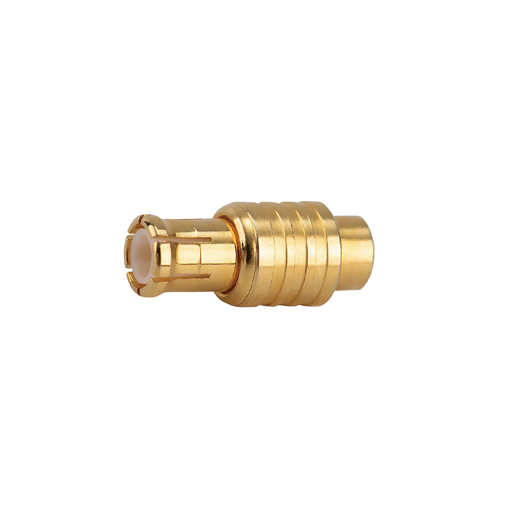
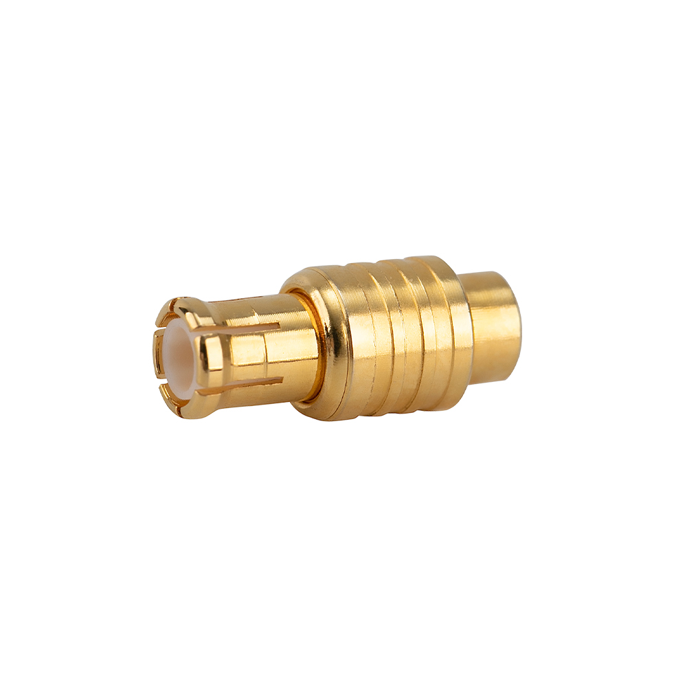
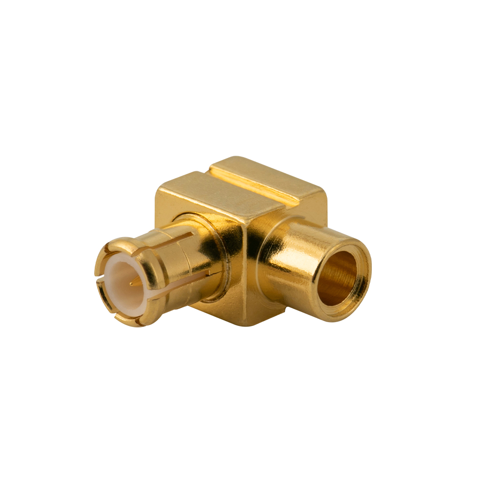
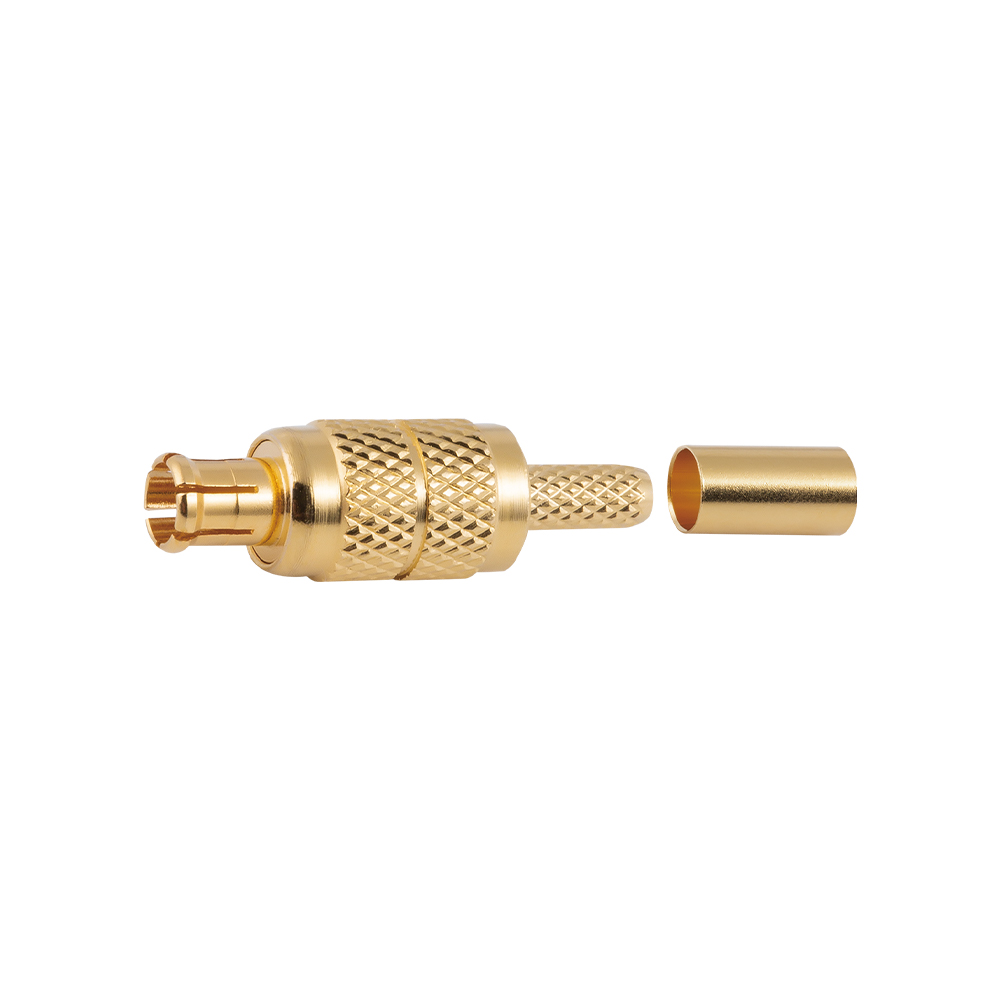
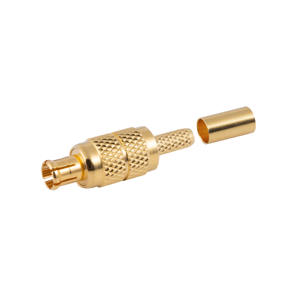
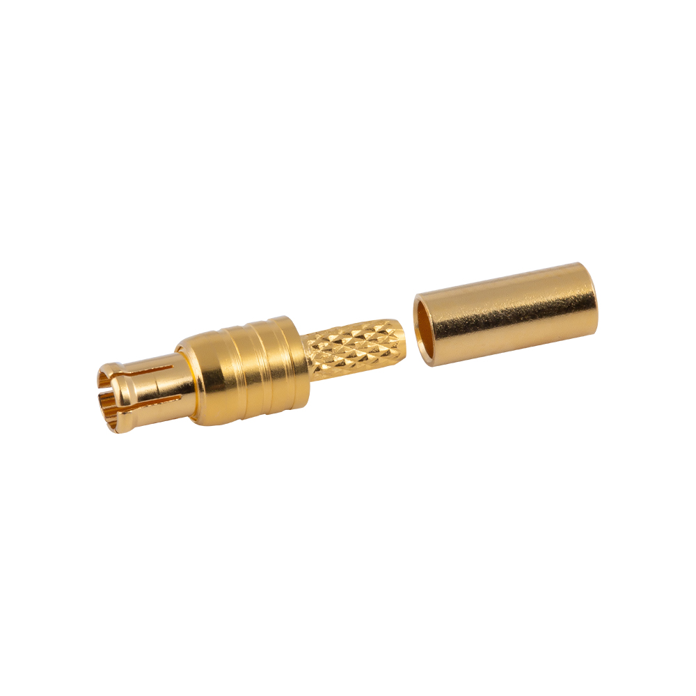
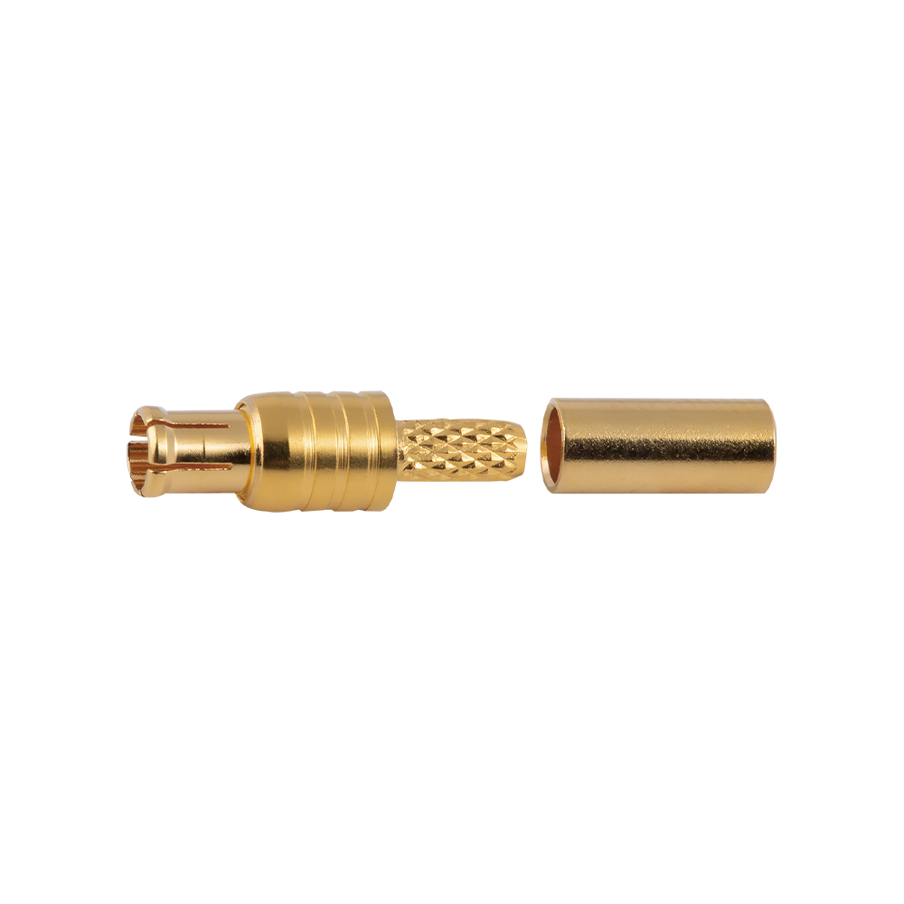
TYPE MCX connector is a kind of micro-miniature connectors with Snap-on coupling. Characteristic impedance is 50Ώ or 75Ώ .The characteristic of connectors is in small volume、light weight, concise structure, easy to use. They are widely used in the Global Position System, Digital Personal Computer Network, all kinds of radio instruments, meters, small-sized electronic equipment and WLAN system.

Temperature Range

-55~+155℃(PE Cable -40~+85℃)

Impedance

50Ω,75Ω

Frequency Range

DC~6GHz

Insulation resistance

≥1000MΩ

Insertion loss

0.18 dB/1GHz

VSWR

Straight ≤1.20/1GHz


Right angle ≤1.45/1GHz

Durability(mating)

≥500cycles

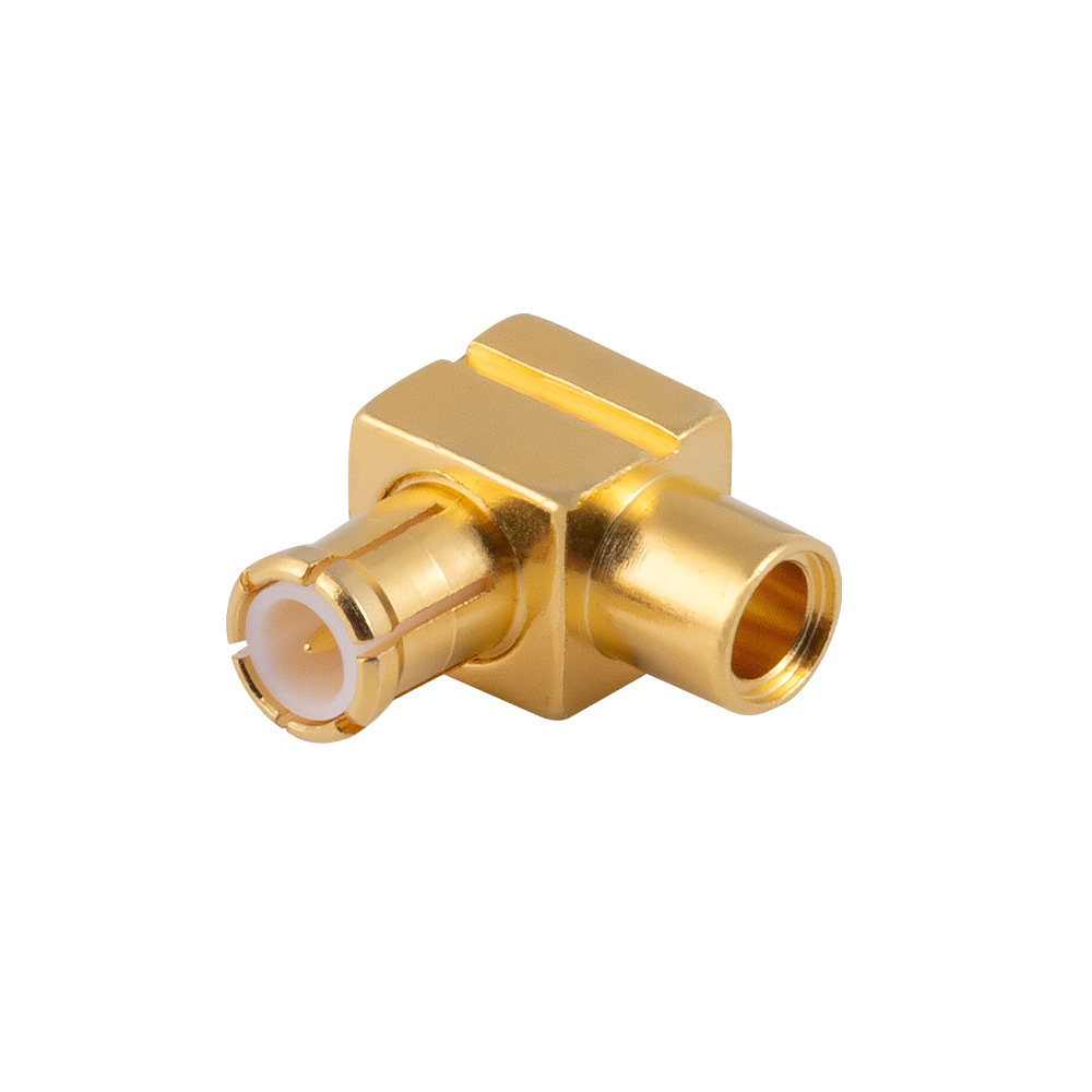
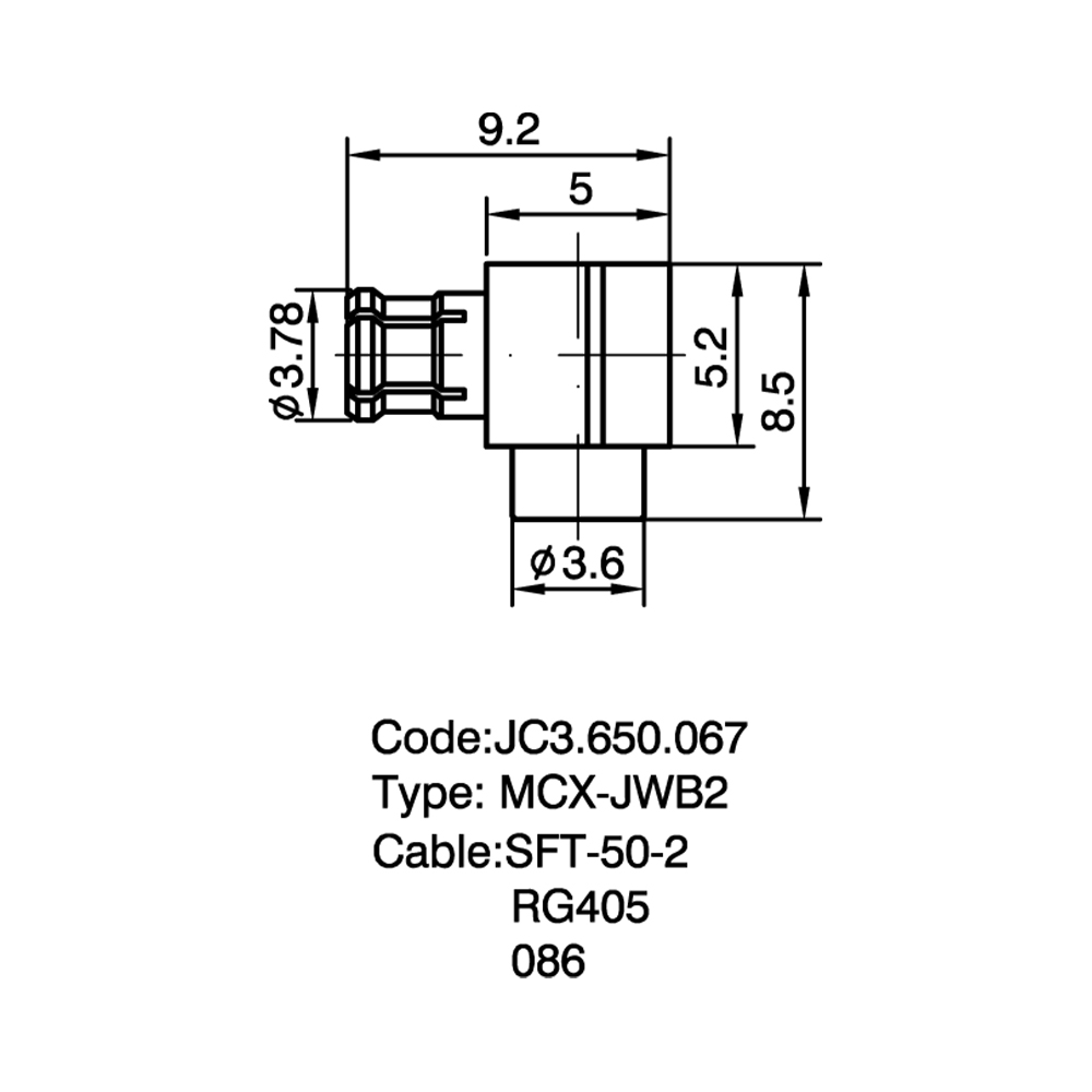
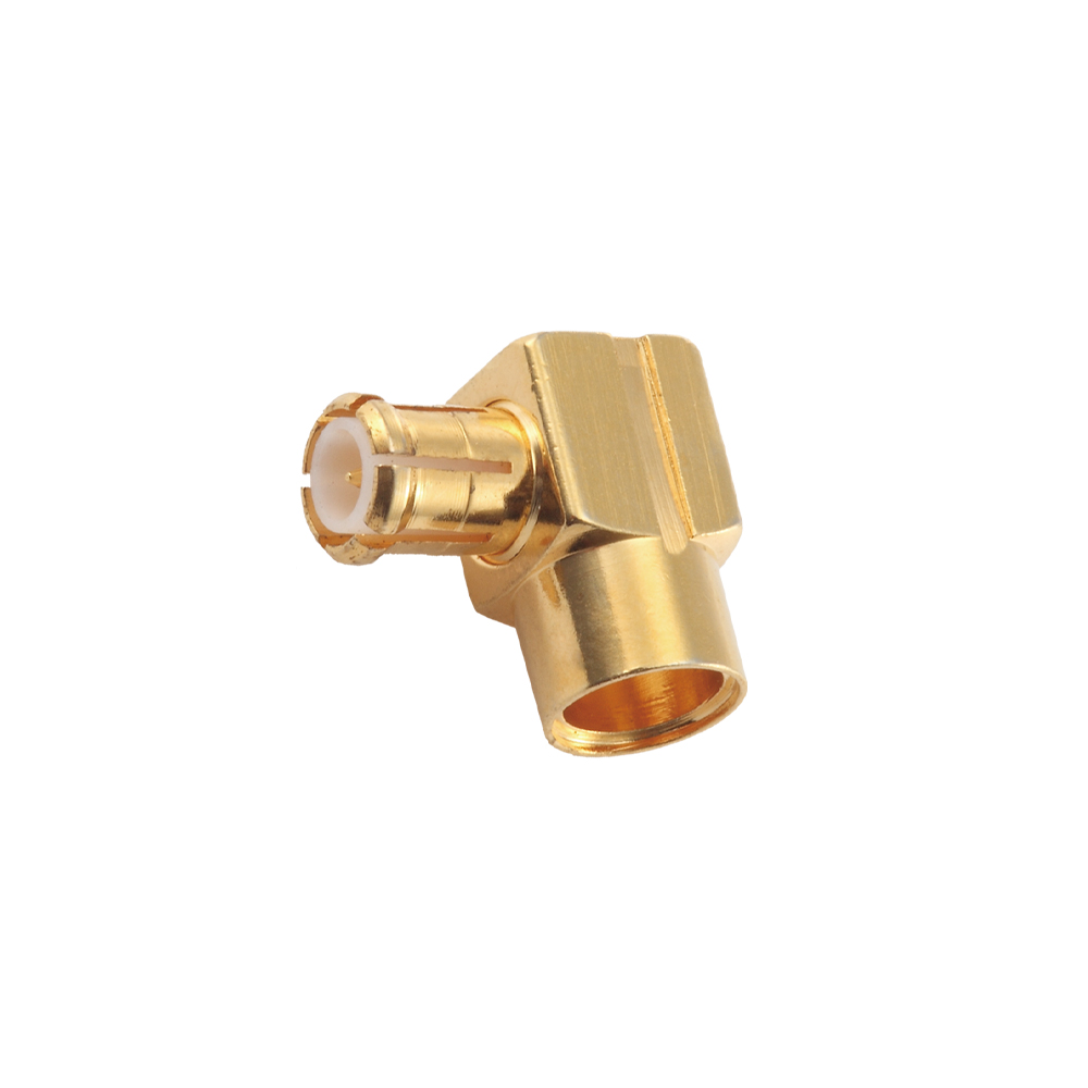
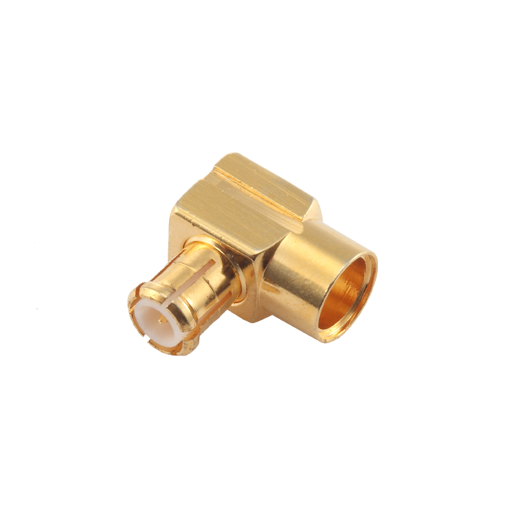
  • JC3.650.067
    MCX-JWB2
    Product parameters > >
    GET A QUOTE
    Major Technical Characteristics
    Temperature Range -55 ~ +155°C (PE Cable -40 ~ +85°C)
    Impedance 50Ω,75Ω
    Frequency Range DC ~ 6GHz
    Working Voltage 250V (50Ω) / 170V (75Ω) at sea level
    Withstanding Voltage 750V (50Ω) / 250V (75Ω) at sea level
    Contact Resistance Center Contact ≤5mΩ
    Outer Contact ≤2.5mΩ
    Insulation Resistance ≥1000MΩ
    Center conductor retention force ≥0.28N
    Engagement force ≤20N
    Disengagement force ≥8N
    Insertion loss 0.18dB/1GHz
    Voltage Standing Wave Ratio Straight ≤1.20/1GHz
    Right angle ≤1.45/1GHz
    Durability ≥500(cycles)

    Material & Plating
    Body Brass Gold plated
    Pin contact Tin bronze Gold plated
    Socket contact Beryllium-copper Gold plated
    Resilient contact Beryllium-copper Gold plated
    Insulator PTFE ——
    Crimp ferrule Copper alloy Nickel/Gold plated
    O-ring sealing 6146 Silicone rubber ——

    Applicable Standard
    CECC 22220
    IEC 61169-36

    JC3.650.067
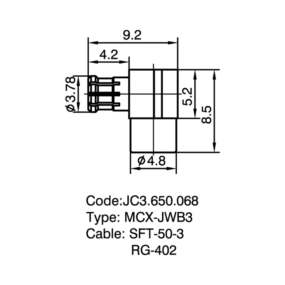
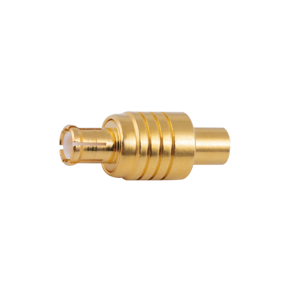
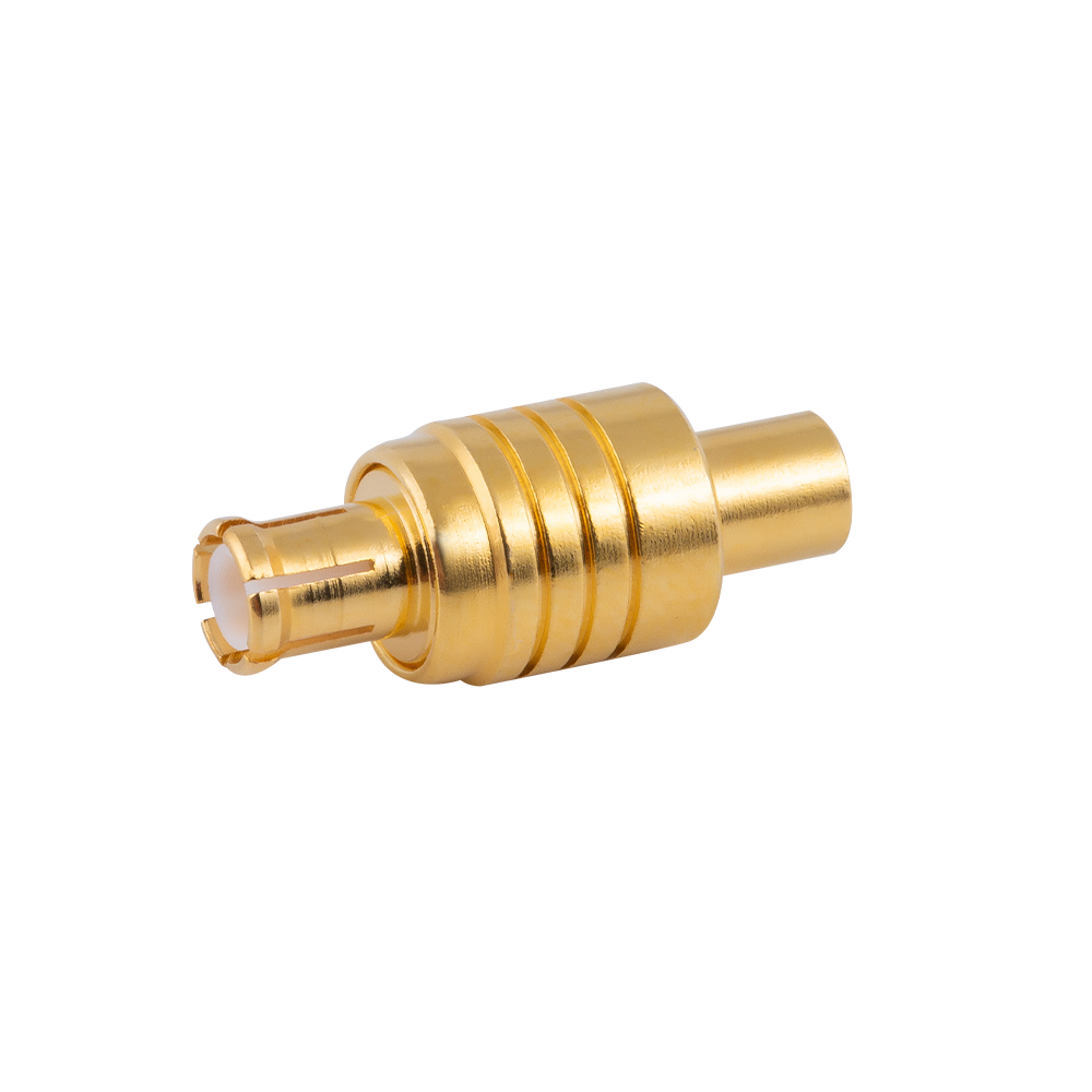
  • JC3.650.068 MCX-JWB3
    GET A QUOTE


    JC3.650.068 MCX-JWB3
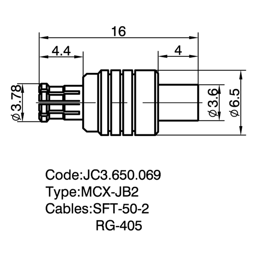
  • JC3.650.069 MCX-JB2
    GET A QUOTE


    JC3.650.069 MCX-JB2
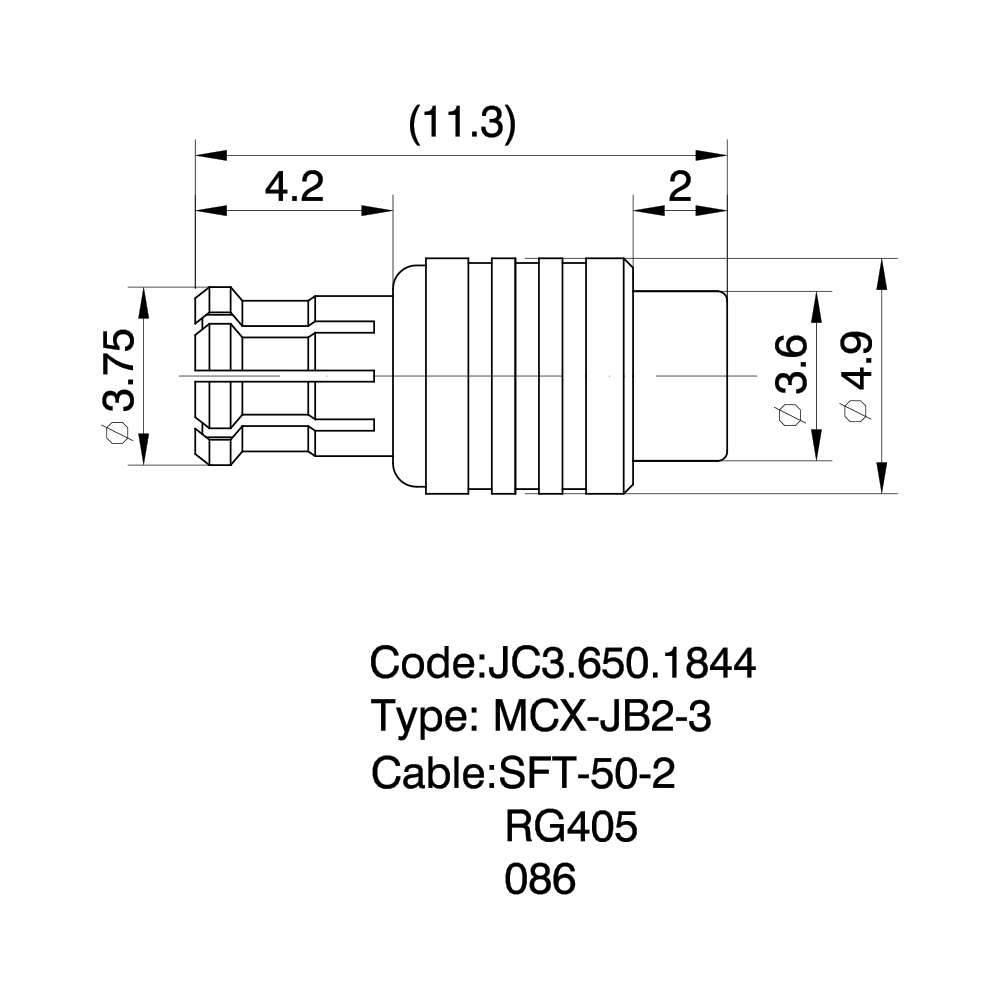
  • JC3.650.1844 MCX-JB2-3
    GET A QUOTE


    JC3.650.1844  MCX-JB2-3
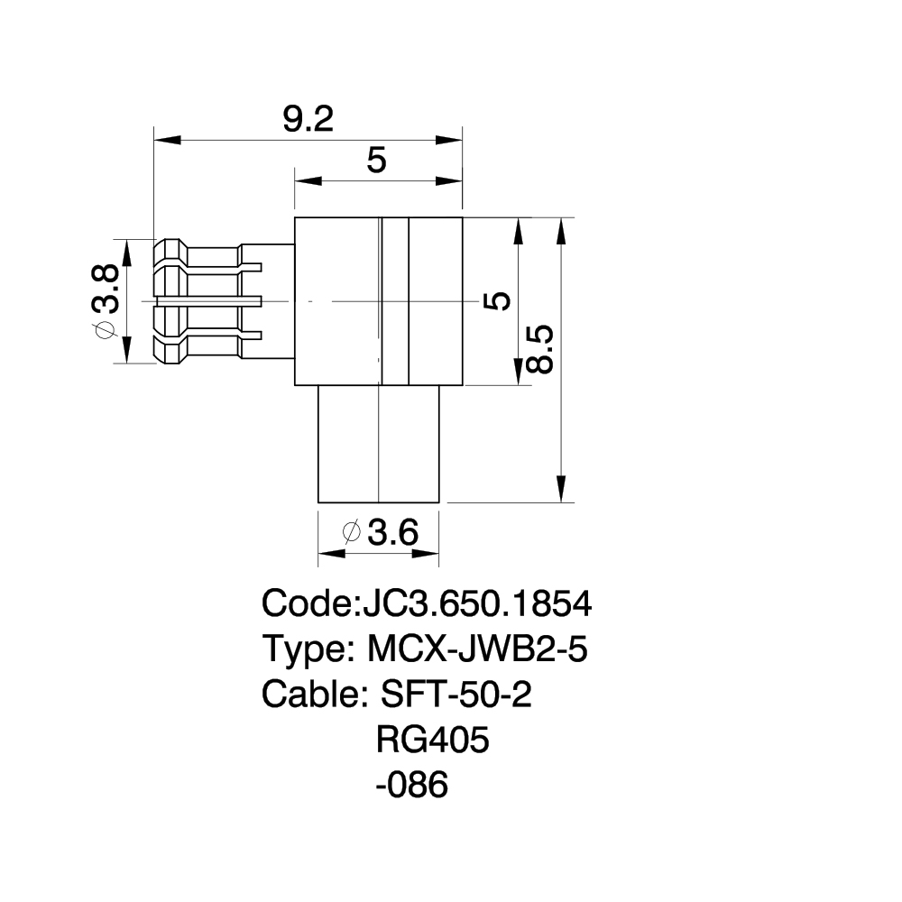
  • JC3.650.1854 MCX-JWB2-5
    GET A QUOTE


    JC3.650.1854  MCX-JWB2-5
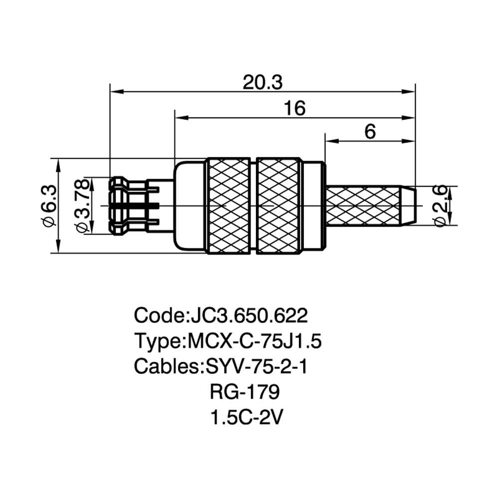
  • JC3.650.622 MCX-C-75J1.5
    GET A QUOTE


    JC3.650.622  MCX-C-75J1.5
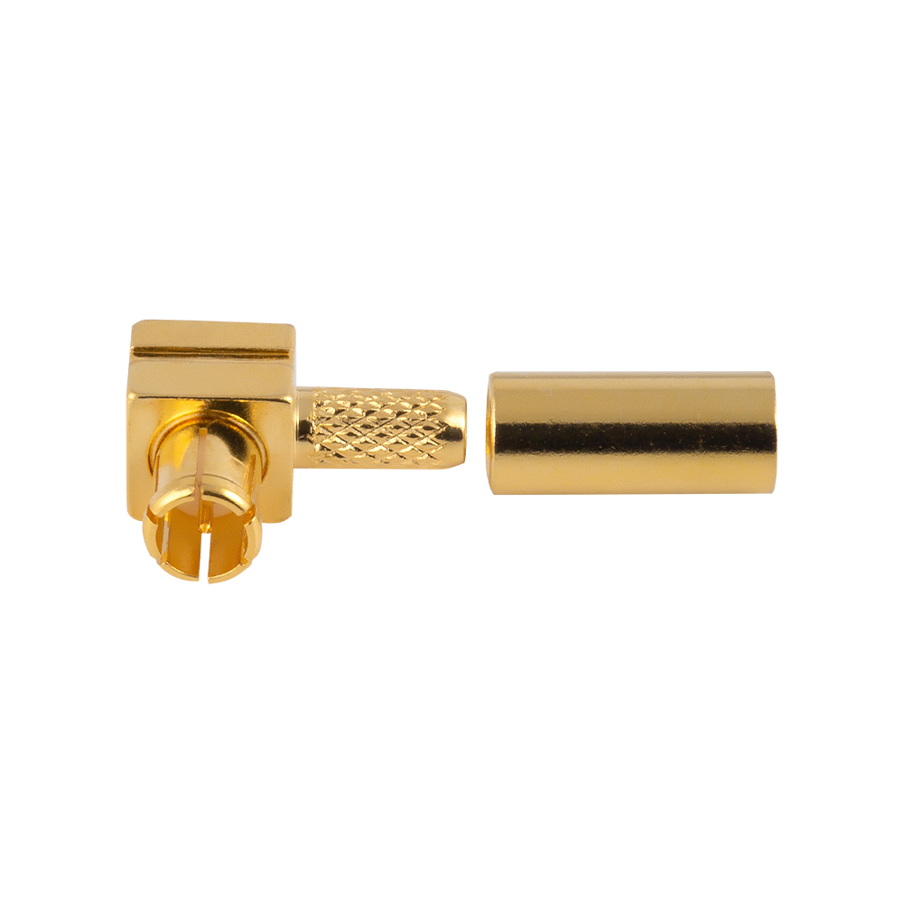
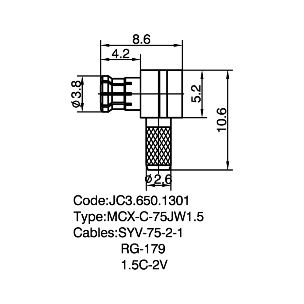
  • JC3.650.1301 MCX-C-75JW1.5
    GET A QUOTE


    JC3.650.1301  MCX-C-75JW1.5
  • JC3.650.1307 MCX-C-75J1.5-1
    GET A QUOTE


    JC3.650.1307  MCX-C-75J1.5-1
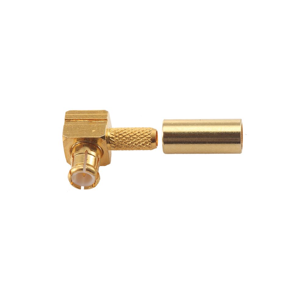
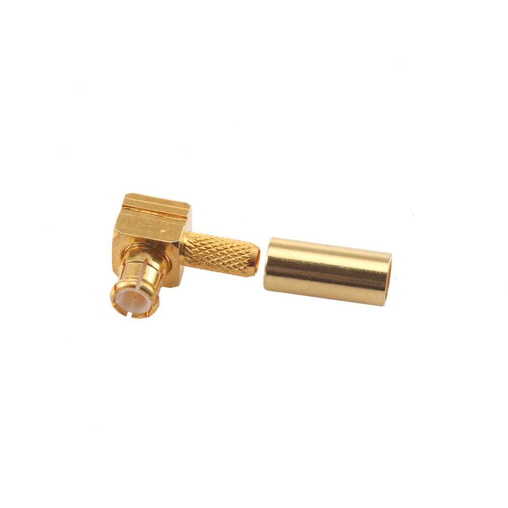
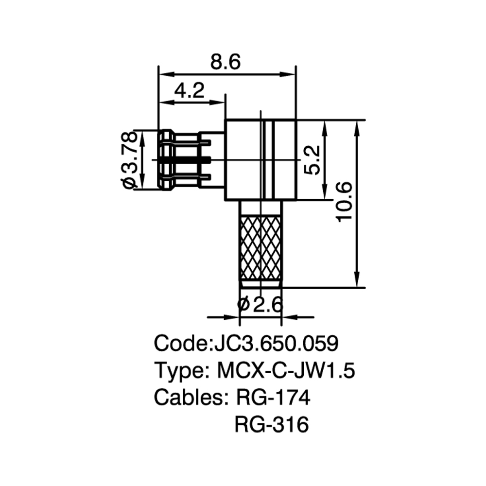
  • JC3.650.059 MCX-C-JW1.5
    GET A QUOTE


    JC3.650.059  MCX-C-JW1.5
About
Yangzhou Jingcheng Electronics Co., Ltd.

Yangzhou Jingcheng Electronics Co., Ltd., a premier China MCX RF Coaxial Connectors Manufacturer and MCX RF Coaxial Connectors Factory, was founded in 1999. It is a high-tech enterprise specializing in the R&D and manufacturing of RF coaxial connectors, cable assemblies, and passive microwave components.
Equipped with a comprehensive R&D and production system, the company has obtained international certifications including ISO9001. Adhering strictly to standards such as MIL, IEC and GB, we offer over 30 product series with more than 2,000 specifications, covering SMA, BNC, N-type and other mainstream models. Our products are widely applied in the fields of communications, aerospace, automotive electronics and beyond, and exported to many countries and regions across Europe, America and Asia.
We uphold the tenet of "Quality as the Foundation, Customers as the Core", committed to providing reliable interconnection solutions and professional services for global clients.

MCX RF Coaxial Connectors Industry knowledge

Overview

MCX RF Coaxial Connectors (Micro Coaxial Connectors) are miniature snap-on coupling RF connectors designed for applications requiring compact size, lightweight construction, and reliable electrical performance. The MCX interface employs a push-on/snap-on mating mechanism that allows quick connection and disconnection while maintaining stable RF characteristics. These connectors are standardized under IEC 61169-36 and CECC 22220 specifications, with characteristic impedance values of 50Ω and 75Ω available. The frequency range typically covers DC to 6 GHz, making MCX RF Coaxial Connectors suitable for a broad spectrum of wireless communication, GPS, automotive electronics, and test & measurement applications.

The design of MCX RF Coaxial Connectors reduces footprint by approximately 30% compared to standard SMB connectors while retaining comparable electrical performance. The snap-on interface provides positive locking with audible and tactile feedback, ensuring secure mating in environments where threaded coupling is impractical. Yangzhou Jingcheng Electronics Co., Ltd., established in 1999 and specializing in RF coaxial connector design and manufacturing, supplies MCX connectors in multiple configurations—including straight and right-angle cable plugs, PCB-mount jacks, panel-mount receptacles, and in-series adapters—supporting both 50Ω and 75Ω impedance requirements.

Common Types & Characteristics

MCX connectors are available in a variety of configurations to address different mounting and cabling requirements. The table below summarizes the principal types and their distinguishing characteristics.

Type Coupling Style Mounting Method Key Characteristics
MCX Straight Cable Plug Snap-on (male) Cable termination (crimp/solder) Inline cable connection; compatible with RG-174, RG-316, RG-178 and semi-rigid cables; straight body minimizes signal path length.
MCX Right-Angle Cable Plug Snap-on (male) Cable termination (crimp/solder) 90-degree cable exit for space-constrained installations; reduces strain on cable assembly; common in enclosed chassis applications.
MCX PCB Jack (Edge/Through-Hole) Snap-on (female) PCB solder (through-hole / surface-mount) Direct PCB integration; available in straight and right-angle orientations; supports automated assembly processes; SMT versions available for high-density layouts.
MCX Panel Mount Receptacle Snap-on (female) Panel/bulkhead mounting Flange or nut-secured mounting on enclosure panels; provides external RF interface; often used with sealing gaskets for environmental protection.
MCX In-Series Adapter Snap-on (both ends) In-line connector interface Female-to-female, male-to-male, or female-to-male configurations; used for test setups, cable extension, and gender conversion; maintains 50Ω or 75Ω impedance continuity.
MCX Bulkhead Connector Snap-on (female/male) Bulkhead feed-through Dual-sided interface passing through enclosure walls; sealed bulkhead options available; supports internal-to-external RF routing without additional cabling.

Core Performance Specifications

Parameter 50Ω Version 75Ω Version
Frequency Range DC – 6 GHz DC – 3 GHz (typical)
Characteristic Impedance 50 Ω 75 Ω
VSWR (Typical) ≤ 1.15 @ 3 GHz / ≤ 1.25 @ 6 GHz ≤ 1.20 @ 2 GHz
Insulation Resistance ≥ 5000 MΩ ≥ 5000 MΩ
Dielectric Withstanding Voltage 500 Vrms (at sea level) 500 Vrms (at sea level)
Contact Resistance (Center) ≤ 5 mΩ ≤ 5 mΩ
Contact Resistance (Outer) ≤ 2.5 mΩ ≤ 2.5 mΩ
Operating Temperature Range -55°C to +155°C -55°C to +155°C
Mating Cycles (Minimum) 500 cycles 500 cycles
Body Material Brass (nickel-plated or gold-plated) Brass (nickel-plated or gold-plated)
Center Contact Material Beryllium copper / Phosphor bronze (gold-plated) Beryllium copper / Phosphor bronze (gold-plated)
Insulator Material PTFE (Polytetrafluoroethylene) PTFE (Polytetrafluoroethylene)

Comparison: MCX vs. MMCX vs. SMA vs. SMB

The following comparison highlights key differences among miniature and sub-miniature RF connector series commonly considered alongside MCX connectors. This comparison assists in identifying the appropriate interface for a given design requirement.

Feature MCX MMCX SMA SMB
Coupling Mechanism Snap-on (push-on) Snap-on (push-on) Threaded (screw-on) Snap-on (push-on)
Frequency Range DC – 6 GHz DC – 6 GHz DC – 18 GHz (standard) DC – 4 GHz
Impedance 50Ω / 75Ω 50Ω 50Ω 50Ω / 75Ω
Outer Diameter (approx.) ~3.8 mm ~2.4 mm ~6.5 mm (interface) ~4.7 mm
Connector Size Miniature Sub-miniature Small (larger than MCX) Small (larger than MCX)
Typical VSWR ≤ 1.15 @ 3 GHz ≤ 1.20 @ 3 GHz ≤ 1.10 @ 6 GHz ≤ 1.25 @ 3 GHz
Connection Speed Fast (snap-on) Fast (snap-on) Moderate (threaded) Fast (snap-on)
Vibration Resistance Moderate Moderate High (thread lock) Moderate
Common Applications GPS, Wi-Fi, automotive, test equipment Embedded antennas, compact wireless modules Test & measurement, microwave links, military Base stations, automotive, medical equipment
Inter-mates with MCX Yes (same series) No (different interface) No (different interface) No (different interface)

Application Scenarios

MCX connectors are deployed across diverse industries where compact RF interconnects with quick-connect capability are required. Typical application areas include:

GPS & GNSS Receivers

MCX connectors serve as the RF interface between GPS/GNSS antenna modules and receiver boards, providing low insertion loss at L-band frequencies (1.2–1.6 GHz). The snap-on coupling facilitates quick antenna replacement in fleet management and telematics systems.

Wireless Communication Devices

In Wi-Fi access points, cellular repeaters, and wireless routers, MCX connectors enable internal RF routing between PCBs and external antennas. The compact footprint suits multi-antenna MIMO configurations within confined device enclosures.

Automotive Electronics

MCX interfaces are used in vehicle infotainment systems, dashboard-mounted GPS modules, and telematics control units. The snap-on mechanism accommodates assembly line efficiency, and the connector's size supports integration into space-limited dashboards.

Test & Measurement Equipment

Spectrum analyzers, vector network analyzers, and RF signal generators may incorporate MCX connectors for internal module interconnection or auxiliary RF ports, where repeatable connection performance up to 6 GHz is required.

Consumer Electronics

Portable media devices, set-top boxes, and digital TV receivers utilize 75Ω MCX connectors for antenna input connections. The push-on design simplifies user interaction while maintaining adequate shielding effectiveness.

Medical Equipment

Diagnostic imaging systems and patient monitoring devices employ MCX connectors for signal transmission within compact equipment housings, where reliable RF performance and small form factor are critical design considerations.

Selection Guide & Key Considerations

Selecting the appropriate MCX connector requires evaluating several technical and mechanical parameters to ensure compatibility with the target application. The following points outline the primary selection criteria:

  1. Impedance Matching: Determine whether the system requires 50Ω or 75Ω impedance. 50Ω is standard for wireless communication and RF test applications, while 75Ω is used in broadcast video and certain consumer equipment. Mismatched impedance can cause signal reflection and degraded VSWR.
  2. Mounting Configuration: Identify the physical mounting requirement—PCB edge-mount, through-hole, surface-mount, panel-mount with flange, or bulkhead feed-through. The mounting style must align with the enclosure design and PCB layout.
  3. Cable Compatibility: For cable-mount connectors, verify compatibility with the specific cable type (e.g., RG-174, RG-316, RG-178, LMR-100, or semi-rigid cables). The connector's ferrule and center contact dimensions must match the cable's outer diameter and center conductor diameter.
  4. Frequency Requirements: Confirm that the connector's rated frequency range (DC–6 GHz for 50Ω MCX) covers the application's operating frequency band with adequate margin. Consider the VSWR specification at the highest frequency of interest.
  5. Body Orientation: Choose between straight and right-angle configurations based on cable routing constraints and space availability within the enclosure. Right-angle connectors reduce vertical clearance requirements.
  6. Plating & Material: Select body and contact plating (nickel, gold, or ternary alloy) based on environmental exposure, corrosion resistance requirements, and budget. Gold-plated beryllium copper center contacts provide optimal conductivity and durability.
  7. Environmental Sealing: For outdoor or high-humidity applications, consider MCX connectors with IP-rated sealing gaskets or bulkhead designs that incorporate O-ring seals.
  8. Mating Cycle Expectation: Evaluate the expected number of connect/disconnect cycles over the product lifetime. MCX connectors are rated for a minimum of 500 mating cycles, suitable for most commercial and industrial applications.

Frequently Asked Questions

Q1: What is the frequency range of MCX RF coaxial connectors?

Standard 50Ω MCX connectors operate from DC to 6 GHz. The 75Ω variant typically supports frequencies up to 3 GHz. The actual usable frequency range depends on the connector design, cable assembly quality, and the VSWR requirements of the specific application. For frequencies above 6 GHz, alternative connector series such as SMA (DC–18 GHz) or 2.92 mm (DC–40 GHz) may be considered.

Q2: Can MCX connectors inter-mate with MMCX or SMA connectors?

No, MCX connectors cannot inter-mate with MMCX, SMA, or SMB connectors. Each series has a distinct interface geometry, coupling mechanism, and outer diameter. MCX uses a snap-on interface with an outer diameter of approximately 3.8 mm, while MMCX has a smaller 2.4 mm interface, and SMA employs a threaded coupling with a larger 6.5 mm interface diameter. For interconnection between different series, a dedicated between-series adapter is required.

Q3: What is the difference between 50Ω and 75Ω MCX connectors?

The primary difference lies in the internal dimensions of the dielectric and center contact, which determine the characteristic impedance. A 50Ω MCX connector has a thicker center contact pin and a different insulator geometry compared to a 75Ω version. The two impedance variants are not inter-matable without risking signal reflection and potential connector damage. 50Ω connectors are used in wireless, test equipment, and general RF applications, while 75Ω connectors are found in video broadcast and certain consumer AV equipment.

Q4: How does the snap-on coupling of MCX compare to threaded SMA in terms of reliability?

Threaded SMA connectors provide higher retention force and greater vibration resistance compared to the snap-on MCX interface. SMA connectors maintain consistent contact pressure under mechanical stress, making them the preferred choice in high-vibration environments such as aerospace and military applications. MCX snap-on coupling offers faster mating and demating, which is advantageous in production environments and applications requiring frequent reconfiguration. For stationary or moderate-vibration settings, the MCX snap-on mechanism delivers adequate reliability over its rated 500+ mating cycles.

Q5: What cable types are compatible with MCX connectors?

MCX cable connectors are designed to accommodate a range of flexible and semi-rigid coaxial cables, including RG-174, RG-178, RG-316, RG-188, LMR-100, and equivalent metric cable types. The selection of the correct ferrule and center contact size is essential for achieving a secure crimp and maintaining specified VSWR performance. For custom cable assemblies, Yangzhou Jingcheng Electronics Co., Ltd. offers cable assembly services with MCX connectors terminated to customer-specified cable types and lengths.

Q6: Are MCX connectors RoHS and REACH compliant?

Yes, MCX connectors supplied by Yangzhou Jingcheng Electronics Co., Ltd. are manufactured in compliance with RoHS (Restriction of Hazardous Substances) Directive 2011/65/EU and REACH (Registration, Evaluation, Authorization, and Restriction of Chemicals) regulations. The plating processes and materials used meet current environmental standards. Compliance documentation is available upon request for specific part numbers.

Manufacturing & Quality Assurance

Yangzhou Jingcheng Electronics Co., Ltd. (JC Company), founded in 1999, has maintained a focused specialization in RF coaxial connector design, development, production, and testing for over two decades. The company's manufacturing infrastructure includes advanced CNC machining centers, automated assembly lines, and high-precision vector network analyzers capable of characterizing connectors up to 50 GHz. This equipment base supports consistent production quality across the complete MCX connector portfolio—from standard catalog items to custom-engineered solutions.

In addition to the MCX series, the product range at Yangzhou Jingcheng Electronics encompasses 2.92 mm, 2.4 mm, 1.85 mm, SMP, SMA, SMZ, CC4, SSMB, MMCX, BNC, TNC, UHF, N, DIN, reverse polarity connectors, attenuators, terminal loads, lightning arresters, push-pull connectors, and high-frequency cable assemblies spanning 0–50 GHz. This breadth of RF interconnect capability allows the company to support customers with multi-series requirements under a single supply chain relationship. Testing equipment includes precision network analyzers, insulation resistance testers, and environmental chambers for thermal cycling validation, ensuring that delivered MCX connectors conform to published electrical and mechanical specifications.