1.0/2.3(CC4) Micro-strip RF Connectors Custom

Home / Products / Coaxial Connectors / 1.0/2.3(CC4) RF Coaxial Connectors / 1.0/2.3(CC4) Micro-strip RF Connectors

1.0/2.3(CC4) Micro-strip RF Connectors Manufacturer

Product Overview
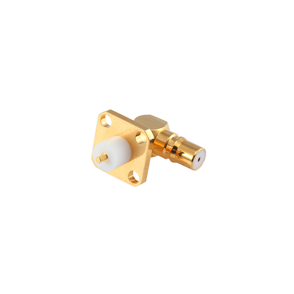
CC4 micro-strip RF connectors are designed to interface coaxial cable with microstrip transmission lines on RF circuit substrates, providing a low-reflection transition between coaxial and planar propagation modes. The extremely compact footprint suits high-integration RF modules and PCB designs where space is constrained and transition performance is critical.

Key Features
Coaxial-to-microstrip transition structure for low-reflection mode conversion
Minimal footprint for high-density microwave module designs
Soldered to the substrate for stable, vibration-insensitive mounting
Snap-on mating for fast connection to external cables

Competitive Advantages
Precision machining maintains impedance continuity at the coaxial-to-microstrip junction, minimizing insertion loss
Inner conductor extension length customizable to match substrate thickness and microstrip line width
Engineering samples available for board-level validation before volume commitment

Typical Applications
Microstrip circuit interfaces in RF transceiver modules
Signal I/O on microwave hybrid integrated circuits (MIC)
Feed ports for phased-array antenna modules
Miniaturized radar and communication front-end modules

FAQ
Q: What is the difference between a micro-strip connector and a PCB connector?
A: A micro-strip connector is optimized for the coaxial-to-planar transmission line transition: the inner conductor connects directly to the microstrip line, and the design prioritizes impedance continuity across that junction. A PCB connector uses through-hole pins or SMT pads to mount on a board and connect through standard PCB traces. The two are suited to different circuit architectures.
Q: How is a micro-strip connector attached to the substrate?
A: Typically, the outer conductor flange or base is soldered to the substrate ground plane, and the inner conductor is soldered to the microstrip line. The exact method varies by model; please request the installation drawing for your specific part.
Q: Can the inner conductor extension length be customized for different substrate thicknesses?
A: Yes. Please provide the substrate thickness and microstrip line width; our engineering team will assess and provide a customized design.
Q: Are 2D drawings or 3D models available?
A: 2D engineering drawings are available for standard models; 3D models are available for select types. Please contact the sales team to request.
Q: How long does it take to get samples?
A: Standard model samples are generally available quickly. Custom models require additional lead time depending on the machining complexity; please discuss your timeline with the sales team.

About
Yangzhou Jingcheng Electronics Co., Ltd.

Yangzhou Jingcheng Electronics Co., Ltd., a premier China 1.0/2.3(CC4) Micro-strip RF Connectors Manufacturer and 1.0/2.3(CC4) Micro-strip RF Connectors Supplier, was founded in 1999. It is a high-tech enterprise specializing in the R&D and manufacturing of RF coaxial connectors, cable assemblies, and passive microwave components.
Equipped with a comprehensive R&D and production system, the company has obtained international certifications including ISO9001. Adhering strictly to standards such as MIL, IEC and GB, we offer over 30 product series with more than 2,000 specifications, covering SMA, BNC, N-type and other mainstream models. Our products are widely applied in the fields of communications, aerospace, automotive electronics and beyond, and exported to many countries and regions across Europe, America and Asia.
We uphold the tenet of "Quality as the Foundation, Customers as the Core", committed to providing reliable interconnection solutions and professional services for global clients.

1.0/2.3(CC4) Micro-strip RF Connectors Industry knowledge

1.0/2.3 (CC4) micro-strip RF connectors are subminiature, push-pull coaxial connectors built to the 1.0/2.3 mechanical interface standard, where 1.0 refers to the nominal pin diameter (1.0 mm) and 2.3 refers to the outer sleeve diameter (2.3 mm).

Mating is completed by a single axial push motion rather than a threaded rotation. A spring collet holds the center pin in contact, while a detent groove on the outer sleeve locks against the mating half. This structure allows direct mounting onto micro-strip transmission lines and PCB edges, which is the origin of the "micro-strip" designation for the 1.0/2.3(CC4) series.

Core Performance Parameters

The 1.0/2.3(CC4) connector operates at a 50 Ω characteristic impedance across a frequency range of DC to 6 GHz, with VSWR typically held below 1.5 across the full band.

Typical electrical and mechanical specifications
Parameter Typical Value
Impedance 50 Ω
Frequency Range DC – 6 GHz
VSWR ≤ 1.5
Mating Cycles ≥ 500
Contact Resistance ≤ 3 mΩ

Typical Applications

Due to its compact size and quick-lock coupling, the connector is used in equipment where board space and installation clearance are limited.

  • Base station and remote radio unit (RRU) modules
  • Distributed antenna systems and signal repeaters
  • Test and measurement instrument internal wiring
  • Positioning, broadband access, and other compact RF equipment

Comparison with Other Subminiature Coaxial Interfaces

Compared with snap-on subminiature connectors, the 1.0/2.3(CC4) series uses a smaller outer sleeve and a defined locking detent, which lowers the risk of partial mating in dense board layouts. Compared with threaded subminiature connectors, installation speed is higher, but retention relies on the locking detent rather than torque, so cable-side strain relief should be considered in vibration environments.

Comparison of coupling type, frequency range and outer diameter across subminiature interfaces
Interface Type Coupling Frequency Range Outer Diameter
Push-pull, quick-lock Single-motion push DC–6 GHz 2.3 mm
Snap-on subminiature Push and click DC–6 GHz 3.0–4.5 mm
Threaded subminiature Screw thread DC–18 GHz and above 6.35 mm

Installation and Maintenance

  1. Align the connector axially and push straight in until the locking detent engages.
  2. Disconnect by pulling on the connector body, never on the cable jacket.
  3. Inspect the center pin and outer sleeve periodically for oxidation or loss of spring tension.
  4. Clean contact surfaces with isopropyl alcohol and a lint-free swab.
  5. Replace the connector once mating cycles approach the rated limit or VSWR drifts out of specification.

Frequently Asked Questions

What does the CC4 code refer to?

CC4 is an alternative code name for the 1.0/2.3 connector series, describing the same mechanical and electrical interface.

What is the difference between micro-strip mount and cable mount versions?

Micro-strip mount versions solder directly onto a PCB transmission line, while cable mount versions terminate to coaxial cable for board-to-board connections.

Are these connectors suitable for outdoor use?

Standard versions are intended for indoor enclosures; sealed variants should be selected for outdoor or high-humidity conditions.

Manufacturing Background

Yangzhou Jingcheng Electronics Co., Ltd. produces the 1.0/2.3(CC4) connector series under ISO9001 quality management, following MIL, IEC, and GB reference standards across more than 30 RF coaxial connector series for communications, aerospace, and automotive electronics applications.
