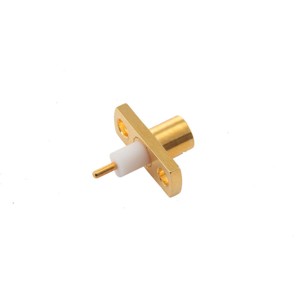
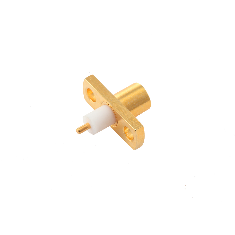
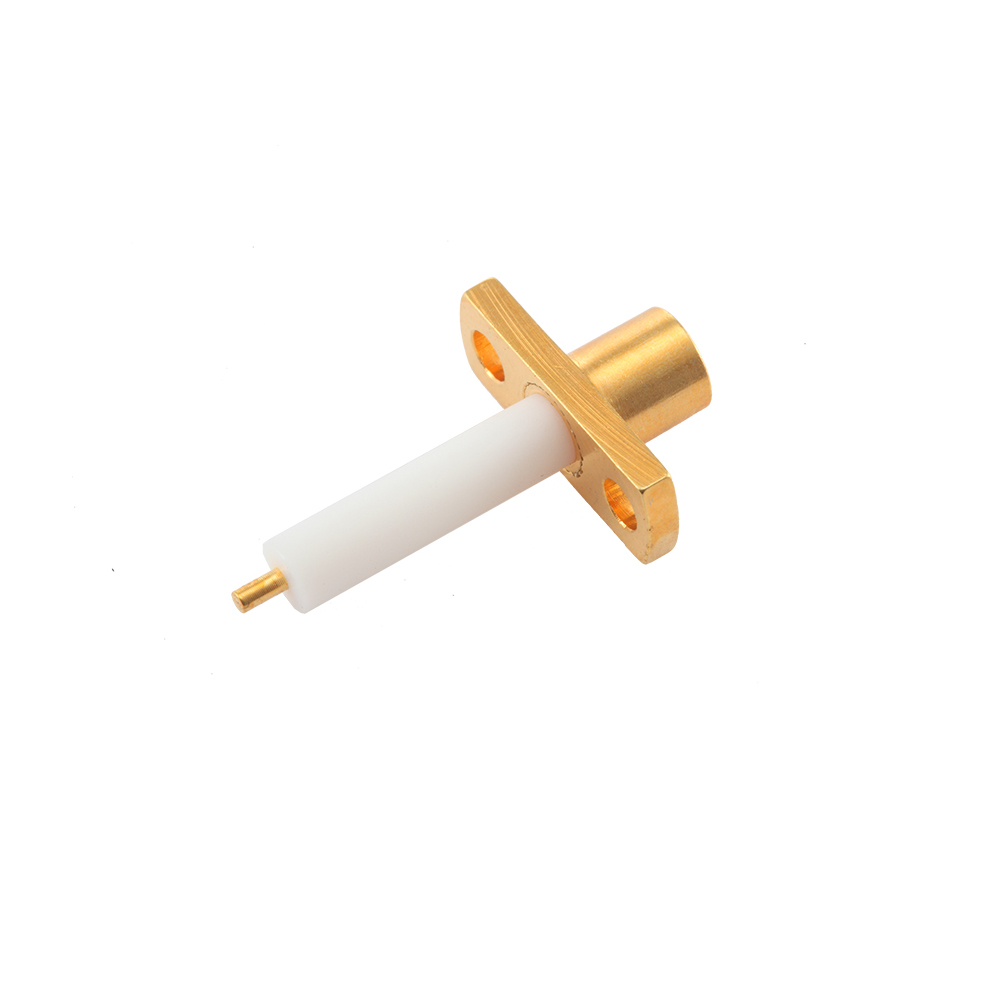
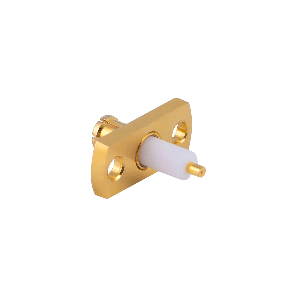
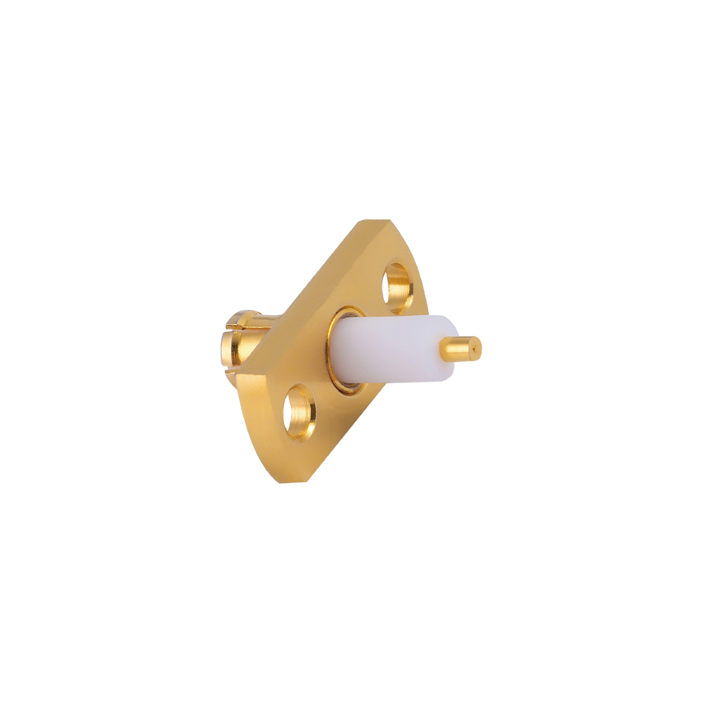
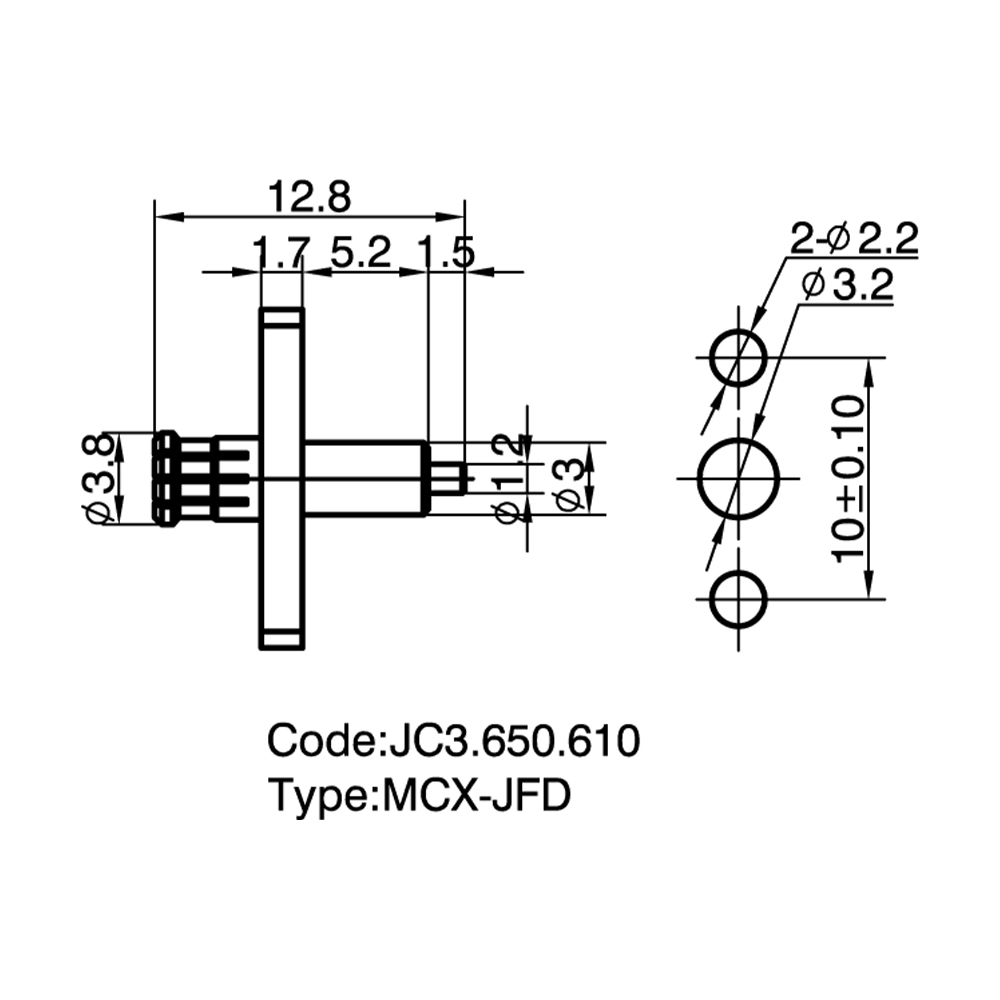
MCX Micro-strip Connectors Custom

Home / Products / Coaxial Connectors / MCX RF Coaxial Connectors / MCX Micro-strip Connectors

MCX Micro-strip Connectors Manufacturer

Product Introduction:
MCX Microstrip connectors are mainly used as signal launch points at the edge of the PCB, responsible for smoothly transitioning microstrip line signals into coaxial cable systems. They are key components in RF module integration.

Product Features:
Ultra-low profile design: Surface-mounted to the PCB without occupying vertical space, facilitating high-density module stacking.
Precision impedance compensation: By optimizing the structure of the center pin, parasitic capacitance in the board transition area is compensated.
Corrosion-resistant materials: The main body is made of gold-plated brass or stainless steel, and the center conductor uses thick gold-plated beryllium copper to ensure stable contact resistance after repeated mating cycles.

Application Advantages:
Signal integrity: The specialized physical transition design effectively suppresses signal reflection, ensuring the purity of high-frequency signals.
High integration: Provides extremely compact physical interfaces for RF amplifiers, mixers, and filters.

Temperature  Range

-55~+155℃(PE Cable   -40~+85℃)

Impedance

50Ω

Frequency Range

DC~6GHz

Insulation resistance

≥1000MΩ

Insertion loss

0.18 dB/1GHz

Voltage Standing Wave Ratio (VSWR)

 Straight ≤1.20/1GHz


 Right  angle ≤1.45/1GHz

 Durability(mating)

≥500 cycles

About
Yangzhou Jingcheng Electronics Co., Ltd.

Yangzhou Jingcheng Electronics Co., Ltd., a premier China MCX Micro-strip Connectors Manufacturer and MCX Micro-strip Connectors Supplier, was founded in 1999. It is a high-tech enterprise specializing in the R&D and manufacturing of RF coaxial connectors, cable assemblies, and passive microwave components.
Equipped with a comprehensive R&D and production system, the company has obtained international certifications including ISO9001. Adhering strictly to standards such as MIL, IEC and GB, we offer over 30 product series with more than 2,000 specifications, covering SMA, BNC, N-type and other mainstream models. Our products are widely applied in the fields of communications, aerospace, automotive electronics and beyond, and exported to many countries and regions across Europe, America and Asia.
We uphold the tenet of "Quality as the Foundation, Customers as the Core", committed to providing reliable interconnection solutions and professional services for global clients.

MCX Micro-strip Connectors Industry knowledge

MCX Micro-strip Connectors are a specialized subcategory of MCX (Micro Coaxial) connectors engineered for direct integration with printed circuit board micro-strip transmission lines. These connectors utilize a snap-on coupling mechanism that enables quick mating and unmating while maintaining reliable electrical performance across a broad frequency range. The micro-strip configuration is specifically designed to transition RF signals between coaxial cable and PCB trace geometries with controlled impedance, minimizing return loss and insertion loss at the board interface.

Yangzhou Jingcheng Electronics Co., Ltd. — a professional RF coaxial connector manufacturer established in 1999 — produces MCX Micro-strip Connectors as part of its comprehensive MCX series portfolio. With in-house advanced manufacturing equipment, precision testing instrumentation up to 50 GHz, and dedicated engineering teams, the company addresses the signal integrity requirements of modern RF and microwave PCB designs. The MCX Micro-strip Connectors supplied by Jingcheng Electronics are available in multiple form factors to accommodate varying board layouts, stack-up thicknesses, and mounting preferences.

Core Performance & Characteristics

Impedance
50 Ω standard; 75 Ω variants available for video and broadcast applications where impedance matching to 75 Ω micro-strip traces is required.
Frequency Range
DC to 6 GHz typical; extended performance variants reach 12 GHz depending on connector design and PCB transition quality.
Coupling Mechanism
Push-on / snap-on coupling with a spring-loaded outer sleeve — enables tool-less mating and a compact footprint compared with threaded alternatives.
VSWR Performance
Typically ≤ 1.3 at 3 GHz and ≤ 1.5 at 6 GHz for a well-designed micro-strip-to-connector transition on standard PCB substrates.
Insertion Loss
≤ 0.2 dB at 3 GHz for the connector body; total link loss depends on PCB trace length, substrate material, and transition design.
Size & Weight
Approximately 30% smaller than SMB connectors; outer diameter of the interface is approximately 3.6 mm, enabling high-density PCB layouts.

Common Types & Mounting Configurations

Type Mounting Style Key Characteristics Typical PCB Application
Straight PCB Vertical Mount Through-hole, center pin soldered to micro-strip trace; ground legs through plated holes to ground plane Perpendicular orientation to board surface; robust mechanical anchoring; suitable for thicker PCBs (1.6 mm and above) Base stations, test equipment, enclosure bulkheads with internal PCB
Right-Angle PCB Mount Through-hole or mixed SMT/through-hole; connector body parallel to board plane Low-profile above-board height; ideal for space-constrained enclosures; good mechanical stability from multiple ground pins Handheld devices, compact RF modules, portable communication equipment
Surface-Mount (SMD/SMT) Fully surface-mountable; center conductor pad and ground pads soldered directly to PCB top layer Compatible with automated pick-and-place assembly; reduced parasitic inductance compared to through-hole; requires careful pad design for impedance continuity High-volume manufacturing, IoT devices, SDR modules, wireless sensors
Edge-Mount (End-Launch) Soldered at the board edge; center pin contacts the micro-strip trace at the PCB edge; ground contacts solder to top and/or bottom ground planes Minimizes trace length from connector to active circuitry; excellent high-frequency performance due to reduced transition discontinuity; board edge must be properly plated High-frequency modules, evaluation boards, RF test fixtures, phased array feed networks
Bulkhead-Mount with Micro-strip Tail Panel/bulkhead mounting with extended center conductor tail for soldering to PCB micro-strip line Combines panel sealing with internal PCB connectivity; center pin length can be customized to span the gap between enclosure wall and PCB Sealed enclosures, outdoor RF equipment, avionics, marine communication systems

Comparison: MCX Micro-strip vs. Related PCB-Mount Connector Series

Parameter MCX Micro-strip MMCX Micro-strip SMB PCB Mount SMA PCB Mount
Interface Outer Diameter ~3.6 mm ~2.4 mm ~4.8 mm ~6.35 mm (1/4 inch)
Coupling Type Snap-on (push-on) Snap-on (push-on) Snap-on (push-on) Threaded (screw-on)
Typical Frequency Max 6 GHz (extendable to 12 GHz) 6 GHz (extendable to 12 GHz) 4 GHz 18 GHz (26.5 GHz for precision grades)
PCB Footprint Density High — ~30% smaller than SMB Very High — smallest of the group Moderate Lower — larger footprint required
Mating Cycle Durability ~500 cycles typical ~500 cycles typical ~500 cycles typical ~500–1000 cycles
Best Suited For Balanced size-performance for general RF PCB designs Ultra-compact designs where PCB real estate is extremely limited Legacy systems and where larger interface is acceptable High-frequency precision applications requiring threaded reliability

Application Scenarios

Telecommunications Infrastructure
Used in base station transceiver modules, repeater units, and small-cell backhaul equipment where multiple RF paths are routed on multi-layer PCBs with controlled-impedance micro-strip traces. The snap-on mechanism facilitates field servicing without specialized tools.
Wireless & IoT Devices
Integrated into Wi-Fi access points, Bluetooth modules, ZigBee coordinators, and LoRa gateways. SMD micro-strip variants enable fully automated assembly lines, supporting high-volume production targets for consumer and industrial IoT products.
Test & Measurement Equipment
Employed in spectrum analyzers, vector network analyzers, signal generators, and RF switch matrices. Edge-mount MCX micro-strip connectors are frequently selected for evaluation boards and calibration fixtures due to their low transition discontinuity.
Automotive & Transportation
Applied in GPS/GNSS antenna connections, tire pressure monitoring system receivers, in-vehicle infotainment modules, and V2X (vehicle-to-everything) communication units. Bulkhead micro-strip variants serve applications requiring both environmental sealing and internal PCB connectivity.
Avionics & Defense Systems
Deployed in airborne communication radios, radar signal processing boards, and electronic warfare subsystems. The combination of compact footprint and robust snap-on retention meets the size and weight constraints of airborne platforms.
Medical RF Equipment
Found in MRI coil interfaces, RF ablation generators, and wireless patient monitoring telemetry. The non-magnetic material options (with appropriate plating selections) support MR-conditional device requirements.

Selection Guidelines & Key Considerations

1. Impedance Matching Requirements
Confirm whether the system operates at 50 Ω or 75 Ω. The micro-strip trace width on the PCB must be calculated based on the chosen substrate dielectric constant (εr), substrate thickness, and copper weight to achieve the target characteristic impedance. The connector's transition geometry should be reviewed against the PCB stack-up to minimize impedance discontinuity at the launch point.
2. Frequency Band & Signal Bandwidth
Evaluate the highest frequency component of the signal, including harmonics for non-sinusoidal waveforms. While MCX connectors are rated to 6 GHz standard, edge-mount configurations with optimized PCB transitions can support higher frequencies. For applications above 12 GHz, consider whether an SMA or 2.92 mm series micro-strip connector is more appropriate.
3. Mounting Orientation & Enclosure Constraints
Determine whether a vertical (straight) or right-angle orientation is needed based on the enclosure layout and board-to-connector spatial relationship. Right-angle configurations reduce the profile height above the PCB, which is relevant for slim enclosures. Edge-mount types place the connector interface flush with the enclosure wall, often eliminating the need for internal cabling.
4. PCB Thickness & Material
Through-hole MCX micro-strip connectors are designed for specific PCB thickness ranges (commonly 1.0 mm to 2.4 mm). Surface-mount variants are less dependent on board thickness but require careful pad and solder mask design. High-frequency PCB materials (e.g., Rogers RO4000 series, PTFE-based laminates) may be specified for applications above 3 GHz to reduce dielectric loss along the micro-strip trace.
5. Plating & Material Specifications
Body materials are typically brass with nickel underplate and gold flash on the contact surfaces. For corrosive environments or extended temperature ranges, specify connectors with stainless steel bodies or enhanced gold plating thickness. The center contact plating directly affects contact resistance and long-term reliability. Yangzhou Jingcheng Electronics Co., Ltd. offers multiple plating options to address different environmental and durability requirements.
6. Assembly Process Compatibility
SMD micro-strip connectors are compatible with reflow soldering profiles (lead-free or leaded), while through-hole types require wave soldering or manual soldering. Verify that the connector's insulator material (PTFE or LCP) can withstand the peak reflow temperatures of the chosen solder process. LCP insulators are typically specified for lead-free reflow profiles with peak temperatures around 260°C.

Technical Specifications — Quick Reference

Specification Typical Value / Range Remarks
Characteristic Impedance 50 Ω (standard); 75 Ω (optional) 75 Ω variants for broadcast/video per IEC 61169
Frequency Range DC – 6 GHz (standard); up to 12 GHz (extended) Performance beyond 6 GHz depends on PCB transition design
VSWR (Voltage Standing Wave Ratio) ≤ 1.3 @ DC–3 GHz; ≤ 1.5 @ 3–6 GHz Measured at connector reference plane with matched micro-strip launch
Insertion Loss ≤ 0.2 dB @ 3 GHz (connector only) Excludes PCB trace loss
Dielectric Withstanding Voltage 750 Vrms (at sea level) Per IEC 61169-36 test conditions
Insulation Resistance ≥ 1000 MΩ Measured at 500 V DC
Contact Resistance (Center) ≤ 5 mΩ (initial) Gold-plated beryllium copper or phosphor bronze contact
Contact Resistance (Outer) ≤ 2.5 mΩ (initial) Spring-loaded outer conductor contact
Temperature Range -65°C to +165°C Depends on insulator material (PTFE: upper range; LCP: reflow-compatible)
Body Material Brass (standard); Stainless Steel (optional) Stainless steel for enhanced corrosion resistance
Insulator Material PTFE or LCP LCP for SMD reflow compatibility; PTFE for wider temperature range
Plating (Body) Nickel underplate + Gold flash; alternatives available Selective gold plating on contact surfaces per customer specification

PCB Design Considerations for Micro-strip Transitions

Achieving optimal signal integrity with MCX micro-strip connectors requires attention to the following PCB layout factors:

  • Micro-strip Trace Width Calculation: The trace width must be computed using the PCB substrate's dielectric constant (εr), substrate height (h), and copper thickness to achieve the target impedance (50 Ω or 75 Ω). Tools such as a micro-strip impedance calculator or electromagnetic simulator should be used. Ground plane continuity beneath the trace is essential — any splits or voids in the ground plane under the micro-strip line will cause impedance discontinuities.
  • Connector Launch Pad Design: The pad geometry where the connector center pin contacts the PCB should be optimized to minimize capacitive or inductive discontinuities. A tapered transition from the pad to the micro-strip trace can reduce return loss. For surface-mount types, the ground pad layout should provide a low-inductance return path — multiple vias stitching the ground pad to the internal ground plane are recommended.
  • Via Placement & Ground Stitching: For through-hole and edge-mount connectors, ground via placement around the connector body affects the quality of the ground reference at the transition. Vias should be placed as close to the ground pins as practical. For edge-mount connectors, plated castellations or edge plating on the PCB improve the ground connection.
  • Substrate Selection for High Frequency: For applications operating above 3 GHz, low-loss PCB materials (tan δ < 0.004) such as Rogers RO4350B, RO4003C, or Isola Astra MT77 are often selected. Standard FR-4 may exhibit higher dielectric loss and greater variation in εr across different batches, affecting impedance consistency.
  • Solder Mask Clearance: Solder mask should be cleared from the micro-strip trace and the connector pad area to avoid affecting the effective dielectric constant above the trace. A clearance of at least 0.2 mm around the trace is typical for controlled-impedance designs.

Frequently Asked Questions

Q: What distinguishes MCX Micro-strip Connectors from standard MCX connectors?
A: Standard MCX connectors are general-purpose coaxial interfaces that can be used with various cable types and mounting styles. MCX Micro-strip Connectors are a specific subcategory where the connector's center conductor and ground reference are designed to interface directly with a PCB micro-strip transmission line. The key distinction lies in the connector's PCB-side geometry: the center pin is positioned and dimensioned to land on a controlled-impedance micro-strip trace, and the ground arrangement is optimized to provide a continuous ground reference from the coaxial structure to the PCB ground plane. This specialization reduces impedance discontinuity at the board transition compared with a generic PCB-mount connector that is not explicitly designed for micro-strip launch.
Q: How does the micro-strip transition affect overall system VSWR?
A: The micro-strip transition is a source of impedance discontinuity because the electromagnetic field configuration changes from the coaxial mode (TEM) in the connector to the quasi-TEM mode of the micro-strip line on the PCB. Any mismatch at this junction contributes to the overall VSWR. The magnitude of this effect depends on the connector's launch design, the accuracy of the PCB trace width, the via placement, and the quality of the ground plane. A well-designed MCX micro-strip connector with an optimized PCB layout can achieve a VSWR contribution below 1.15 at 3 GHz from the transition alone. Poorly designed transitions can degrade VSWR to 1.4 or higher. Electromagnetic simulation of the complete connector-to-PCB transition is recommended for applications above 6 GHz.
Q: Can MCX micro-strip connectors be used with flexible PCB substrates?
A: Yes, MCX micro-strip connectors can be mounted on flexible PCB substrates (e.g., polyimide-based flex circuits), provided the mechanical attachment is properly engineered. The primary considerations are: the flex PCB must be adequately supported near the connector to prevent mechanical stress on the solder joints during mating and unmating; the micro-strip trace on a flex substrate may have different impedance characteristics due to the thin dielectric and the absence of a rigid ground plane support; and a stiffener may be required behind the connector mounting area. Surface-mount MCX micro-strip connectors are generally preferred for flex applications because they avoid the mechanical stress concentrations associated with through-hole pins in flexible materials. For designs requiring repetitive flexing near the connector, strain relief features should be incorporated.
Q: What is the difference between edge-mount and vertical-mount MCX micro-strip connectors in terms of RF performance?
A: Edge-mount (end-launch) MCX micro-strip connectors generally offer superior high-frequency performance because the center conductor can be positioned with minimal distance between the coaxial reference plane and the micro-strip trace on the PCB edge. This short transition path reduces parasitic inductance and capacitance. Vertical-mount connectors route the signal through a longer internal path from the connector interface down to the PCB surface, which introduces additional electrical length and potential for impedance variation. However, vertical-mount configurations are mechanically more versatile for many enclosure designs. The choice between them involves a trade-off between electrical performance and mechanical packaging constraints. For applications above 8 GHz, edge-mount configurations are typically recommended.
Q: What plating options are available for MCX micro-strip connectors, and how do they affect solderability?
A: Common plating configurations include: (1) nickel underplate with gold flash over the entire body — provides good solderability and corrosion resistance; (2) selective gold plating on contact surfaces with tin-lead or pure tin on solder tails — optimizes solder wetting while maintaining gold contact reliability; (3) silver plating on the body for enhanced conductivity in specific applications. The solder tails or pads of MCX micro-strip connectors must have a solderable finish compatible with the intended soldering process. For lead-free reflow soldering, pure tin or nickel-gold finishes are widely used. It is important to note that thick gold plating on solder surfaces can lead to gold embrittlement in solder joints; therefore, selective plating that limits gold thickness on solder tails is often specified. Yangzhou Jingcheng Electronics Co., Ltd. provides guidance on plating selection based on the customer's assembly process and end-use environment.
Q: Are MCX micro-strip connectors available in reverse polarity configurations?
A: Yes, reverse polarity (RP) MCX micro-strip connectors are available. In a reverse polarity MCX connector, the gender of the center contact is reversed — a male body contains a female center socket, and a female body contains a male center pin. Reverse polarity configurations are frequently used in wireless networking equipment (Wi-Fi, Bluetooth) to comply with regulatory requirements that discourage unauthorized antenna modifications. Yangzhou Jingcheng Electronics Co., Ltd., with its comprehensive reverse polarity series manufacturing capability, supplies RP-MCX micro-strip connectors in various mounting configurations, including vertical through-hole, right-angle, and surface-mount types.