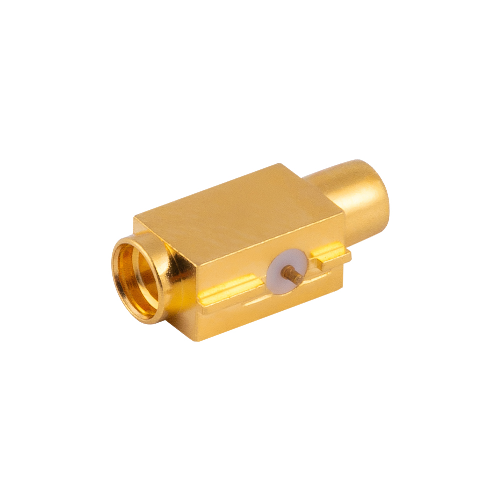
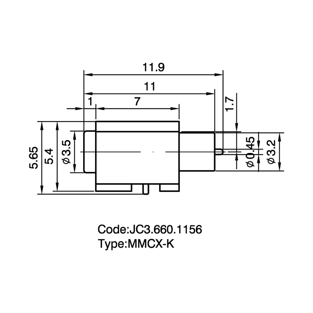
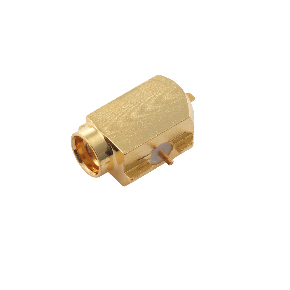
MMCX RF Coaxial Switch Socket Custom

Home / Products / Coaxial Connectors / MMCX RF Coaxial Connectors / MMCX RF Coaxial Switch Socket

MMCX RF Coaxial Switch Socket Manufacturer

Product Introduction:
This is a special PCB socket with an integrated automatic switching function. When a plug is inserted, the internal mechanical structure automatically disconnects the onboard antenna link and switches the signal to an external test port.

Product Features:
Mechanical switch durability: The internal spring contacts are made of high-performance beryllium copper and have undergone tens of thousands of elastic fatigue tests, ensuring precise and reliable switching action.
High isolation: In the disconnected state, the ports provide extremely high isolation, preventing signal interference and false detection.
Compact package: Complex mechanical switching functions are realized within a very small form factor, suitable for automated SMT assembly.

Application Advantages:
Automated production line testing: RF performance calibration and conducted testing can be performed through the switch socket without disassembling the enclosure.
Multi-function switching: Enables easy switching between built-in antennas and external high-gain antennas, enhancing device flexibility.

Temperature Range

-55~+155℃(PE Cable   -40~+85℃)

Impedance

50Ω

Frequency Range

DC~6GHz

Insulation resistance

≥1000MΩ

Insertion loss

0.18 dB/1GHz

Voltage Standing Wave Ratio (VSWR)

Straight ≤1.25/3GHz


Right angle ≤1.43/3GHz

 Durability(mating)

≥500 cycles

About
Yangzhou Jingcheng Electronics Co., Ltd.

Yangzhou Jingcheng Electronics Co., Ltd., a premier China MMCX RF Coaxial Switch Socket Manufacturer and MMCX RF Coaxial Switch Socket Supplier, was founded in 1999. It is a high-tech enterprise specializing in the R&D and manufacturing of RF coaxial connectors, cable assemblies, and passive microwave components.
Equipped with a comprehensive R&D and production system, the company has obtained international certifications including ISO9001. Adhering strictly to standards such as MIL, IEC and GB, we offer over 30 product series with more than 2,000 specifications, covering SMA, BNC, N-type and other mainstream models. Our products are widely applied in the fields of communications, aerospace, automotive electronics and beyond, and exported to many countries and regions across Europe, America and Asia.
We uphold the tenet of "Quality as the Foundation, Customers as the Core", committed to providing reliable interconnection solutions and professional services for global clients.

MMCX RF Coaxial Switch Socket Industry knowledge

Category Overview

The MMCX RF Coaxial Switch Socket is a micro-miniature radio frequency interconnect component that integrates a mechanical switching mechanism within a standard MMCX socket form factor. Operating at a nominal impedance of 50 ohms, this category of products is designed to provide a compact solution for routing RF signals between two paths—typically between an internal antenna circuit and an external antenna connection. When a mating MMCX plug is inserted, the internal switch actuates, redirecting the signal path from the default closed circuit to the external port. This functionality eliminates the need for separate external switching circuitry in space-constrained designs.

Yangzhou Jingcheng Electronics (JC), established in 1999, manufactures MMCX RF Coaxial Switch Socket products within its comprehensive RF coaxial connector portfolio. The company's production of these switch sockets is supported by precision manufacturing equipment and high-accuracy testing facilities, ensuring that each unit meets the dimensional and electrical specifications required for reliable operation across its designated frequency range, typically extending to 6 GHz and in certain configurations reaching 12 GHz. The MMCX switch socket shares the same snap-on coupling mechanism as the standard MMCX series, providing a secure connection with a 360-degree rotational capability after mating, which aids in cable routing within compact enclosures.

The MMCX RF Coaxial Switch Socket finds application across wireless communication modules, GPS receivers, Bluetooth devices, handheld test equipment, and IoT terminals where antenna switching or test point access is required. Its micro-miniature footprint—significantly smaller than MCX or SMA counterparts—makes it suitable for high-density PCB layouts and portable device architectures where board real estate is at a premium.

Common Types & Characteristics

Mounting Type PCB Orientation Termination Method Key Characteristics
PCB Vertical Mount Straight / Vertical Through-hole soldering Switch mechanism oriented perpendicular to PCB plane; suitable for top-panel antenna access; robust mechanical anchoring via through-hole legs.
PCB Right-Angle Mount Right-Angle / Horizontal Through-hole soldering Mating axis parallel to PCB surface; ideal for edge-panel configurations; reduces overall enclosure height profile.
SMT (Surface-Mount) Straight or Right-Angle Surface-mount reflow soldering Compatible with automated pick-and-place assembly; requires precise pad layout; suitable for high-volume production; may incorporate reinforced ground pads for mechanical stability.
Edge-Mount / End-Launch Edge-aligned Soldering to PCB edge pads Positioned at PCB perimeter for direct external access; minimizes signal path length; often used in modules requiring panel-mount antenna connections without cabling.
Bulkhead / Panel Mount Panel-fixed Cable connection to PCB Mounted through enclosure wall with locking nut; switch socket accessible externally; internal connection via flexible cable assembly to the main PCB.

Comparative Analysis: MMCX Switch Socket vs. Related Connectors

3.1 MMCX Switch Socket vs. Standard MMCX Connector

Feature MMCX RF Coaxial Switch Socket Standard MMCX Connector
Switching Function Integrated mechanical switch (NC default) No switching function
Signal Paths Two selectable paths Single fixed path
Typical Application Internal/external antenna switching Direct antenna or cable connection
Coupling Mechanism Snap-on (identical to MMCX) Snap-on
Frequency Range DC to 6 GHz (typical), up to 12 GHz DC to 6 GHz (typical), up to 12 GHz
Insertion Loss (at 6 GHz) Typically ≤ 0.3 dB (switch path) Typically ≤ 0.2 dB

3.2 MMCX Switch Socket vs. MCX vs. SMA

Parameter MMCX Switch Socket MCX Connector SMA Connector
Outer Diameter (approx.) ~2.4 mm ~3.6 mm ~6.35 mm (1/4 inch)
Coupling Type Snap-on (quick connect/disconnect) Snap-on Threaded screw coupling
Frequency Range DC to 6 GHz (extended to 12 GHz) DC to 6 GHz DC to 18 GHz (or higher)
Integrated Switch Yes No (standard MCX) No
Board Footprint Smallest among the three Medium Largest
Typical Use Case Portable devices with antenna switching GPS, automotive, consumer wireless Test equipment, base stations, lab use
Durability (Mating Cycles) Typically 500 cycles Typically 500 cycles Typically 500+ cycles

Application Scenarios

The integration of a switch within the MMCX socket form factor addresses design requirements where automatic signal path selection is needed without additional board-level switching components. Typical deployment scenarios include:

• Wireless Communication Modules

Used in cellular and Wi-Fi modules where an internal PCB antenna is the default, and an external antenna can be connected via the MMCX switch socket for improved range or testing.

• GPS / GNSS Receivers

Enables switching between an internal ceramic patch antenna and an external active GPS antenna, commonly found in vehicle tracking and surveying equipment.

• Bluetooth & IoT Devices

Facilitates conducted RF testing and antenna substitution in compact IoT sensors, wearables, and Bluetooth audio products during development and production.

• Handheld Test & Measurement

Provides a convenient test port access point in portable spectrum analyzers, signal generators, and field measurement instruments.

• Automotive Telematics

Employed in on-board diagnostic (OBD) dongles and telematics control units where an external antenna connection may supplement an embedded antenna.

• Medical Wireless Devices

Supports antenna switching in wireless patient monitoring equipment and implant communication modules where compact size is critical.

Selection Guide & Key Considerations

Selecting the appropriate MMCX switch socket for a given design involves evaluating several technical parameters. Yangzhou Jingcheng Electronics provides consultation support to assist design engineers in identifying the correct configuration from its MMCX product range. The following factors should be assessed during the selection process:

Selection Criterion Description Guidance
Operating Frequency The frequency range over which the switch socket must maintain specified VSWR and insertion loss. Verify that the selected MMCX switch socket is rated for the target frequency band. Standard types cover DC to 6 GHz; extended-range types reach 12 GHz.
PCB Mounting Style The physical orientation and soldering method on the printed circuit board. Choose vertical, right-angle, SMT, or edge-mount based on enclosure design and antenna port location. Consider assembly process compatibility (reflow vs. wave soldering).
Switch Configuration The default state of the internal switch when no plug is inserted. Most MMCX switch sockets use a normally-closed (NC) configuration connecting to the internal antenna path. Confirm switch logic matches the system design.
Impedance Characteristic impedance of the transmission path. Standard is 50 ohms, matching most RF systems. Confirm system impedance to avoid mismatch losses.
VSWR / Return Loss Measure of impedance matching quality across the frequency band. Review VSWR specifications—typical values are ≤ 1.3:1 at 6 GHz. Lower VSWR indicates better matching and less signal reflection.
Insertion Loss Signal attenuation introduced by the switch socket in the signal path. Evaluate insertion loss at the highest operating frequency. Switch sockets exhibit slightly higher loss than non-switch types due to the internal contact path.
Mating Cycle Durability Number of connect/disconnect operations the socket can withstand while remaining within spec. Standard rating is 500 cycles minimum. For applications requiring frequent mating, verify durability specifications with the manufacturer.
Environmental Conditions Temperature range, humidity, and other ambient factors. MMCX switch sockets typically operate from -40°C to +85°C. For extended temperature ranges, consult JC's product specifications.

Frequently Asked Questions

Q1: What is the function of the switch integrated into an MMCX RF Coaxial Switch Socket?

The integrated switch provides automatic signal path selection.在没有插头插入时, the switch maintains a normally-closed (NC) connection—typically routing the signal to an internal antenna or a default circuit path. When a mating MMCX plug is inserted, the mechanical action of insertion opens the NC contact and establishes a connection to the external path via the plug. This eliminates the need for a separate external RF switch component on the PCB.

Q2: What frequency range does a typical MMCX switch socket support?

Standard MMCX switch sockets operate effectively from DC to 6 GHz. Extended-performance variants can reach up to 12 GHz. The actual usable frequency range depends on the specific design, materials, and manufacturing precision. Yangzhou Jingcheng Electronics offers MMCX switch socket products with performance verified across the specified frequency bands using precision network analysis equipment.

Q3: How does an MMCX switch socket differ from a standard MMCX connector in terms of insertion loss?

Due to the additional internal switch contact path, an MMCX switch socket exhibits marginally higher insertion loss compared to a standard MMCX connector without a switch. At 6 GHz, typical insertion loss for the switch path is approximately 0.3 dB, whereas a standard MMCX connector may measure around 0.2 dB. This difference is attributable to the extra contact interface within the switch mechanism and should be accounted for in link budget calculations.

Q4: Can MMCX switch sockets be used with automated PCB assembly processes?

Yes, surface-mount (SMT) versions of MMCX switch sockets are designed for compatibility with automated pick-and-place equipment and reflow soldering processes. Through-hole variants can be processed using wave soldering or selective soldering techniques. Proper PCB pad design and solder paste stencil specifications are important for achieving reliable solder joints. JC provides recommended footprint layouts for its MMCX switch socket products.

Q5: What materials are commonly used in MMCX switch socket construction?

Body and contact materials are typically brass or beryllium copper, with gold plating over nickel underplate for reliable electrical contact and corrosion resistance. Insulator materials are generally PTFE or other low-loss dielectric materials suitable for RF frequencies. The specific material composition affects durability, contact resistance, and frequency performance. Yangzhou Jingcheng Electronics selects materials based on the target performance specifications of each MMCX switch socket model.

Q6: What is the typical mating cycle life of an MMCX switch socket?

The standard durability rating for MMCX switch sockets is 500 mating cycles minimum, after which electrical parameters such as contact resistance and VSWR should remain within specified limits. Actual cycle life can vary based on insertion technique, environmental conditions, and frequency of use. For applications requiring extended durability, consultation with the manufacturer is recommended to identify suitable product variants.

Technical Notes

  • The snap-on coupling mechanism of the MMCX switch socket provides audible and tactile feedback upon proper mating, reducing the likelihood of incomplete connections.
  • After mating, the connector pair allows 360-degree rotation without signal degradation, facilitating flexible cable routing in confined enclosures.
  • PCB layout for MMCX switch sockets should incorporate grounded coplanar waveguide or microstrip transmission line design to maintain impedance continuity from the IC to the connector.
  • The switch contact is a mechanical element subject to wear; for applications with very high mating frequency, periodic inspection of switch performance is advisable.
  • Yangzhou Jingcheng Electronics, with its manufacturing experience dating back to 1999, maintains in-house testing capabilities for RF connectors including VSWR, insertion loss, and isolation measurements across the 0–50 GHz range.