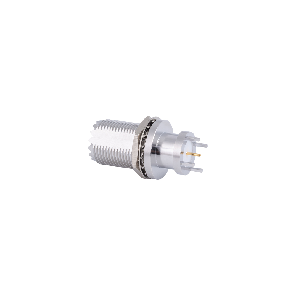
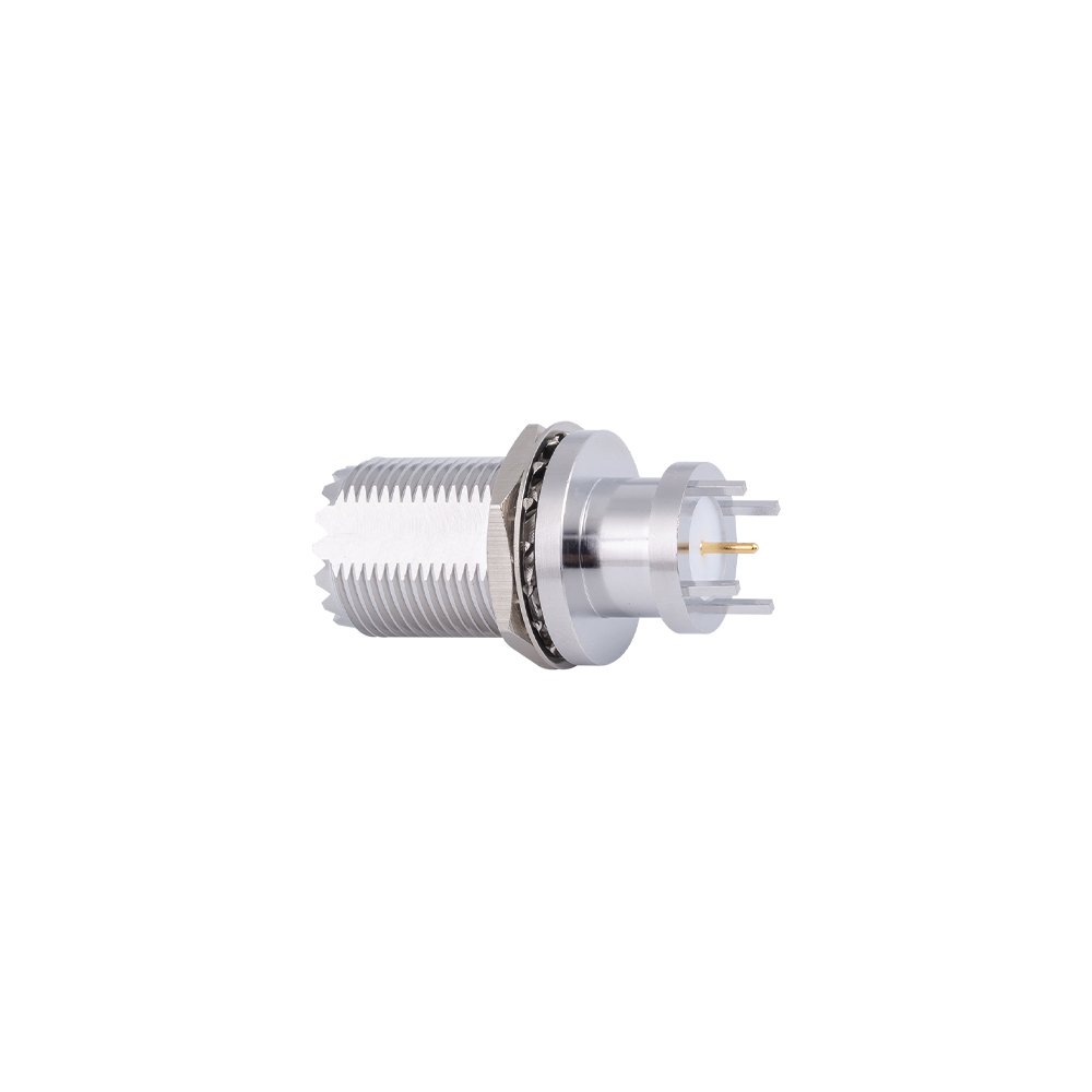
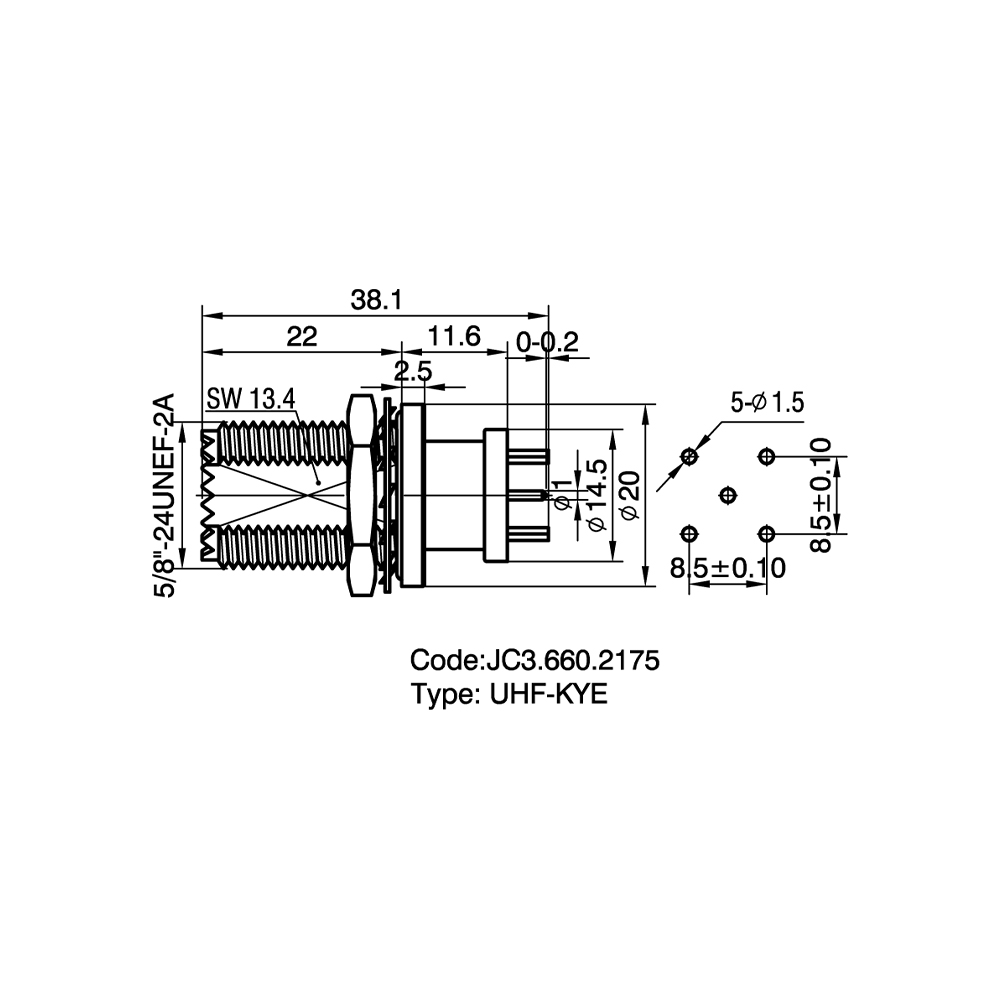
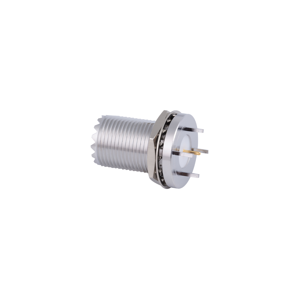
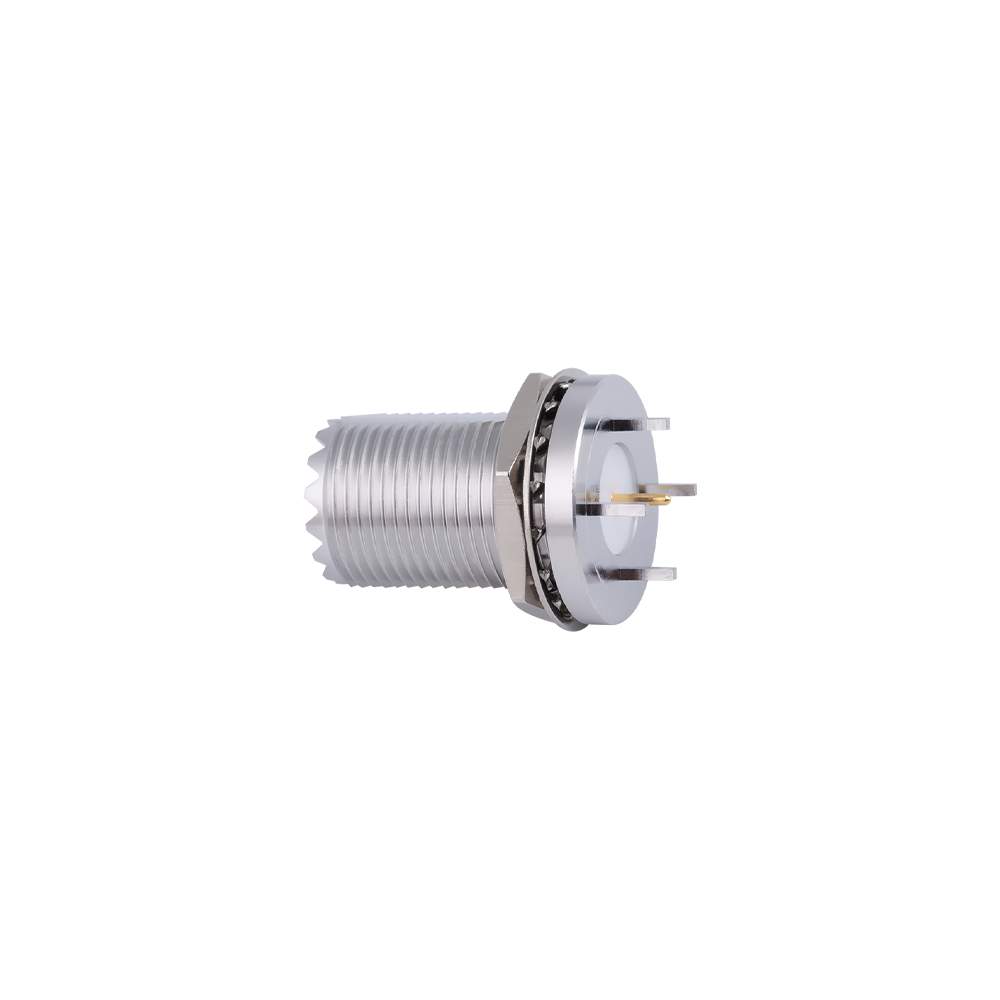
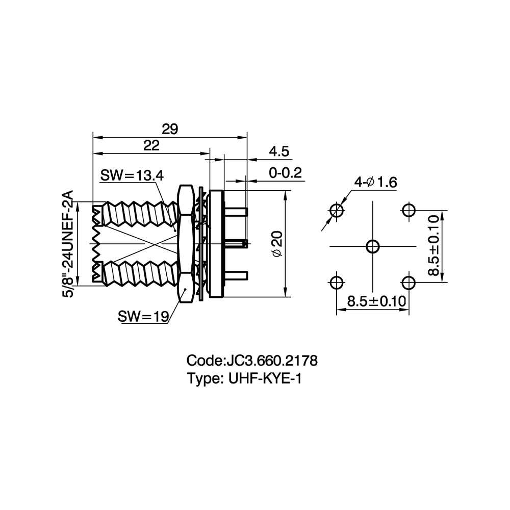
UHF PCB connectors are UHF-series coaxial connectors designed for direct mounting onto a printed circuit board rather than onto a cable end or an equipment panel. The category includes through-hole and surface-mount versions in straight and right-angle body orientations, with center pin and ground tabs configured for soldering directly to PCB pads and plated-through holes, providing a fixed RF interface between board-level circuitry and an external cable or antenna connection.
Function and Working Principle
A UHF PCB connector carries the signal path from the board trace to the center contact through a solder pin that passes through, or sits on, a designated PCB pad, while the connector's outer shell is grounded to the board's ground plane through one or more solder tabs or through-hole ground pins. This fixed solder-mount arrangement removes the need for an internal cable jumper between the board and the panel-mounted feed-through connector used in other UHF connector categories. The external thread of the UHF PCB connector remains exposed at the board edge or through a panel cutout, allowing a standard UHF cable plug to mate directly to the board-mounted connector.
Core Performance Characteristics
| Parameter |
Typical Value / Description |
| Frequency range |
DC to 300 MHz |
| Impedance |
Non-constant impedance, nominally treated as 50 Ω |
| Contact resistance |
Center contact ≤ 3 mΩ; outer contact ≤ 2 mΩ |
| Insulation resistance |
≥ 5000 MΩ |
| Dielectric withstanding voltage |
1000–1500 V RMS |
| Mounting orientation |
Straight (vertical) or right-angle (horizontal) |
| Termination style |
Through-hole solder pin/tab, or surface-mount pad |
| Body material |
Brass with nickel or silver plating |
Product Highlights
- Direct board-mount design eliminates the internal cable jumper otherwise needed between a bulkhead connector and the circuit board.
- Straight and right-angle orientations accommodate different board layouts and enclosure clearance requirements.
- Through-hole ground pins or tabs provide a stable mechanical fixing point in addition to the electrical ground path.
- Compatible with standard UHF cable plugs at the external mating interface, allowing use with existing UHF-series cable assemblies.
- Suitable for reflow or hand-soldering processes depending on the pin and pad configuration selected.
Variants and Detailed Comparison
Within the UHF PCB connectors category, the primary variants are distinguished by mounting orientation and termination method.
| Type |
Orientation |
Termination |
Typical Use |
| Straight PCB mount |
Vertical, perpendicular to board |
Through-hole solder pin and ground tabs |
Board edge-mount feed-through, test fixtures |
| Right-angle PCB mount |
Horizontal, parallel to board |
Through-hole solder pin and ground tabs |
Low-profile enclosures, front-panel board layouts |
| Surface-mount (SMT) type |
Straight or right-angle |
Solder pads for reflow assembly |
Automated production lines, compact board designs |
UHF PCB Connectors vs. UHF Bulkhead Mount Connectors
| Category |
Mounting Reference |
Internal Wiring |
Typical Role |
| UHF PCB connectors |
Printed circuit board |
None; connector solders directly to board |
Board-level RF input/output point |
| UHF bulkhead mount connectors |
Equipment panel or chassis |
Internal jumper cable to board required |
Panel feed-through with cable routing to internal circuitry |
UHF PCB connectors are selected when the connector interfaces directly with the circuit board, while UHF bulkhead mount connectors are selected when the connector interfaces with a panel and an internal cable link is used to reach the board. Both categories present the same external UHF threaded interface for cable mating.
Application Cases
- Mobile radio circuit boards: A right-angle UHF PCB connector is soldered near the board edge to provide an antenna feed point that aligns with a panel cutout on the radio housing.
- Test and measurement fixtures: Straight UHF PCB connectors are used on fixture boards to allow repeated connection and disconnection of test cables during production testing.
- Amplifier and repeater modules: UHF PCB connectors provide the RF input or output point on amplifier boards installed inside a sealed housing, matched externally to a UHF bulkhead jack on the enclosure.
- Automated board assembly: Surface-mount UHF PCB connectors are placed and reflow-soldered alongside other SMT components during automated production, reducing manual soldering steps.
Installation and Maintenance Guidance
- Verify PCB pad and through-hole layout against the connector's mechanical drawing before board fabrication, since footprint mismatches cannot be corrected after the board is manufactured.
- For through-hole types, ensure the ground pins/tabs are fully seated in their pads prior to soldering to maintain mechanical support and a low-resistance ground path.
- For surface-mount types, follow the recommended reflow temperature profile to avoid dielectric damage from excessive thermal exposure.
- Avoid mechanical stress on the connector body during cable mating and de-mating; repeated torque applied directly to a PCB-mounted connector can stress the solder joints over time.
- Inspect solder joints periodically in equipment subject to vibration, and re-flow or re-solder joints showing cracking or dulling.
- Keep the external mating thread and center contact free of dust, moisture, or corrosion, and clean with a dry cloth or RF-rated contact cleaner before mating a cable plug.
Frequently Asked Questions
What is the difference between straight and right-angle UHF PCB connectors?
A straight type mounts perpendicular to the board, with the mating interface facing away from the board surface, while a right-angle type mounts parallel to the board, directing the mating interface toward the board edge for use in low-profile or front-panel layouts.
Can UHF PCB connectors be reflow-soldered in automated production?
Surface-mount versions are designed for reflow assembly, while through-hole versions are typically hand-soldered or wave-soldered depending on the production process in use.
Do UHF PCB connectors require an internal cable jumper?
No. UHF PCB connectors solder directly to the board, removing the internal cable jumper that is otherwise needed when a UHF bulkhead mount connector is used on the panel.
Are UHF PCB connectors compatible with standard UHF cable plugs?
Yes. The external mating thread on a UHF PCB connector follows the same UHF interface, allowing standard UHF cable plugs to mate directly with the board-mounted connector.
What causes solder joint failure on PCB-mounted UHF connectors?
Common causes include excessive mechanical stress during cable mating/de-mating, vibration over extended service periods, and incorrect reflow or soldering temperature during assembly.
Yangzhou Jingcheng Electronics Co., Ltd. (JC Company), founded in 1999, manufactures UHF PCB connectors together with related UHF, SMA, N-type, BNC, and TNC series connectors, cable assemblies, and passive RF components under ISO9001 quality management, with production referencing MIL, IEC, and GB standards for communication and mobile radio board-level applications.


 English
 中文简体
中文简体