English
 中文简体

An RF engineer once told me that most field failures are not component failures; they are selection failures. Selecting a coaxial cable starts with three decisions: characteristic impedance, cable size, and connector family. Get these three right and the rest of the design has a predictable signal path. Get one wrong and you will be debugging intermittent reflections for weeks.
A coaxial cable and its connector are one assembly, not two parts. A properly matched pair keeps the impedance continuous from the PCB to the antenna or instrument port, while an unmatched combination creates reflections, heating, and intermittent signals. That is why this guide treats the cable and its termination as a single selection process.
Content
- 1 What a Coaxial Cable Is and Why Geometry Matters
- 2 Choose 50 Ohm for RF and 75 Ohm for Video Distribution
- 3 Key Cable Parameters: Loss, Power, Shielding, and Flexibility
- 4 Connector Selection: Match the Cable Bore, Frequency, and Environment
- 5 Shielding and Dielectric Choice Affect Noise Immunity and Stability
- 6 Application-Based Selection Summary
- 7 Practical Purchasing Considerations for Production
- 8 Coaxial Cable Selection FAQ
- 9 Final Selection Checklist
What a Coaxial Cable Is and Why Geometry Matters
A coaxial cable is a cylindrical signal carrier made of four concentric layers: inner conductor, dielectric spacer, conductive shield, and protective jacket; its characteristic impedance is fixed by the ratio of the inner conductor diameter to the shield diameter. Change that ratio, or change the dielectric, and the impedance changes even if the outer diameter stays the same.
The same geometry also controls attenuation and power handling. Larger cables generally have lower loss and higher power capability, but they cost more, weigh more, and bend less easily. This trade-off is the starting point of every practical selection.
Choose 50 Ohm for RF and 75 Ohm for Video Distribution
Use 50 ohm whenever the signal is RF, microwave, or telecommunications, and use 75 ohm for video, broadcast, and cable television distribution. The 50 ohm value is a practical compromise between low attenuation and higher power handling, while 75 ohm reduces loss at video frequencies and has become the standard impedance for CATV infrastructure.
Mixing impedance systems is possible over very short lengths but normally costs return loss. A 75 ohm cable inserted into a 50 ohm system creates a small impedance bump at every transition, which degrades VSWR and adds ripple to the passband.
| Impedance | Market | Typical Cables | Connector Families |
|---|---|---|---|
| 50 ohm | RF/microwave, mobile, Wi-Fi, GPS, test | RG-58, RG-174, RG-213, semi-rigid | SMA, N, TNC, BNC, 7-16 |
| 75 ohm | CCTV, cable TV, broadcast video | RG-59, RG-6, RG-11 | F, BNC, RCA |
Key Cable Parameters: Loss, Power, Shielding, and Flexibility
Compare four electrical parameters first: attenuation, power handling, shielding effectiveness, and impedance stability; then add mechanical flexibility and environmental rating. Attenuation rises with frequency, so a cable selected for 100 MHz can become unusable at 2.4 GHz.
For example, a 10-meter run of RG-58 at 900 MHz can lose on the order of 6 to 7 dB, while RG-213 of the same length loses roughly 2 to 3 dB. The larger conductor and dielectric simply dissipate less RF energy. RG-174 is thinner and lossier than RG-58, which makes it suitable for short pigtail connections rather than long feeder runs.
| Cable | Impedance | Diameter | Flexibility | Typical Use | Loss Trend |
|---|---|---|---|---|---|
| RG-58 | 50 ohm | About 5 mm | Good | Test leads, short RF jumpers | Moderate |
| RG-174 | 50 ohm | About 2.5 mm | Very good | Internal module wiring, GPS pigtails | Higher |
| RG-213 | 50 ohm | About 10 mm | Stiff | Base station feeders, higher power | Lower |
| RG-6 | 75 ohm | About 7 mm | Good | CATV, satellite, long video runs | Lower |
| RG-59 | 75 ohm | About 6 mm | Good | CCTV, short video links | Moderate |
| RG-11 | 75 ohm | About 10 mm | Stiff | Long CATV drops | Lower |
Connector Selection: Match the Cable Bore, Frequency, and Environment
The connector is the most failure-prone part of an RF coaxial assembly, so select it by impedance, frequency range, mechanical coupling, and the exact cable diameter it was designed to fit; then verify plating, torque, and sealing before production. Most connector families are available in versions for flexible and semi-rigid cables, and a good series is rated higher than your actual operating frequency because it is rarely a perfect 50 or 75 ohm line.
Before finalizing the connector family, cross-check the full specification matrix with our RF coaxial connector selection guide, which covers types, specifications, and selection tips in more detail.
| Connector | Impedance | Frequency | Typical Cable | Use |
|---|---|---|---|---|
| BNC | 50 / 75 ohm | Up to 4 GHz | RG-58, RG-59 | Test instruments, video |
| TNC | 50 ohm | Up to 11 GHz | RG-58, RG-213 | Vibration-resistant outdoor links |
| N | 50 ohm | Up to 11 GHz | RG-213, low-loss flexible, semi-rigid | Outdoor antennas, feeders |
| SMA | 50 ohm | Up to 18 GHz | RG-58, RG-174, semi-rigid | Module ports, test equipment |
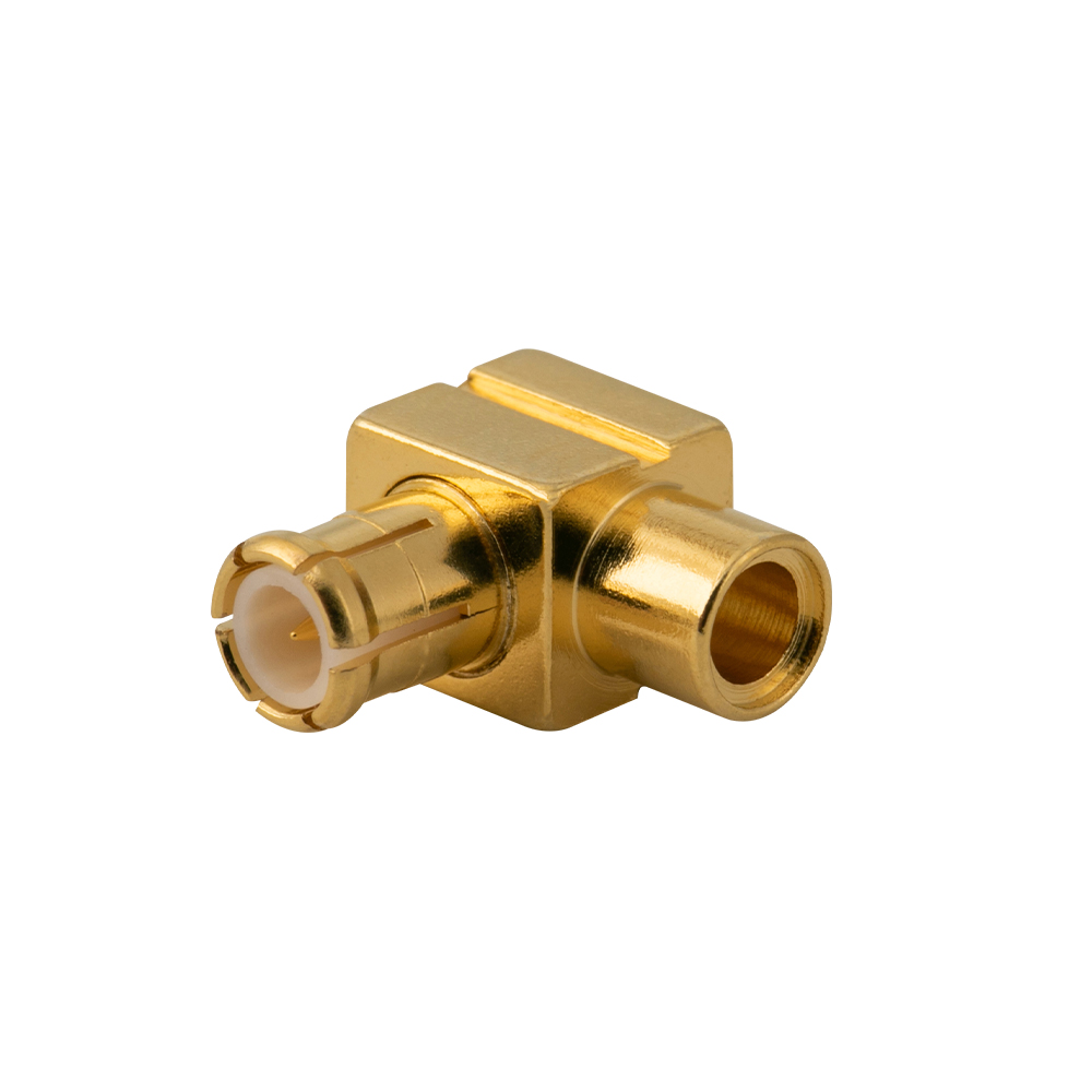
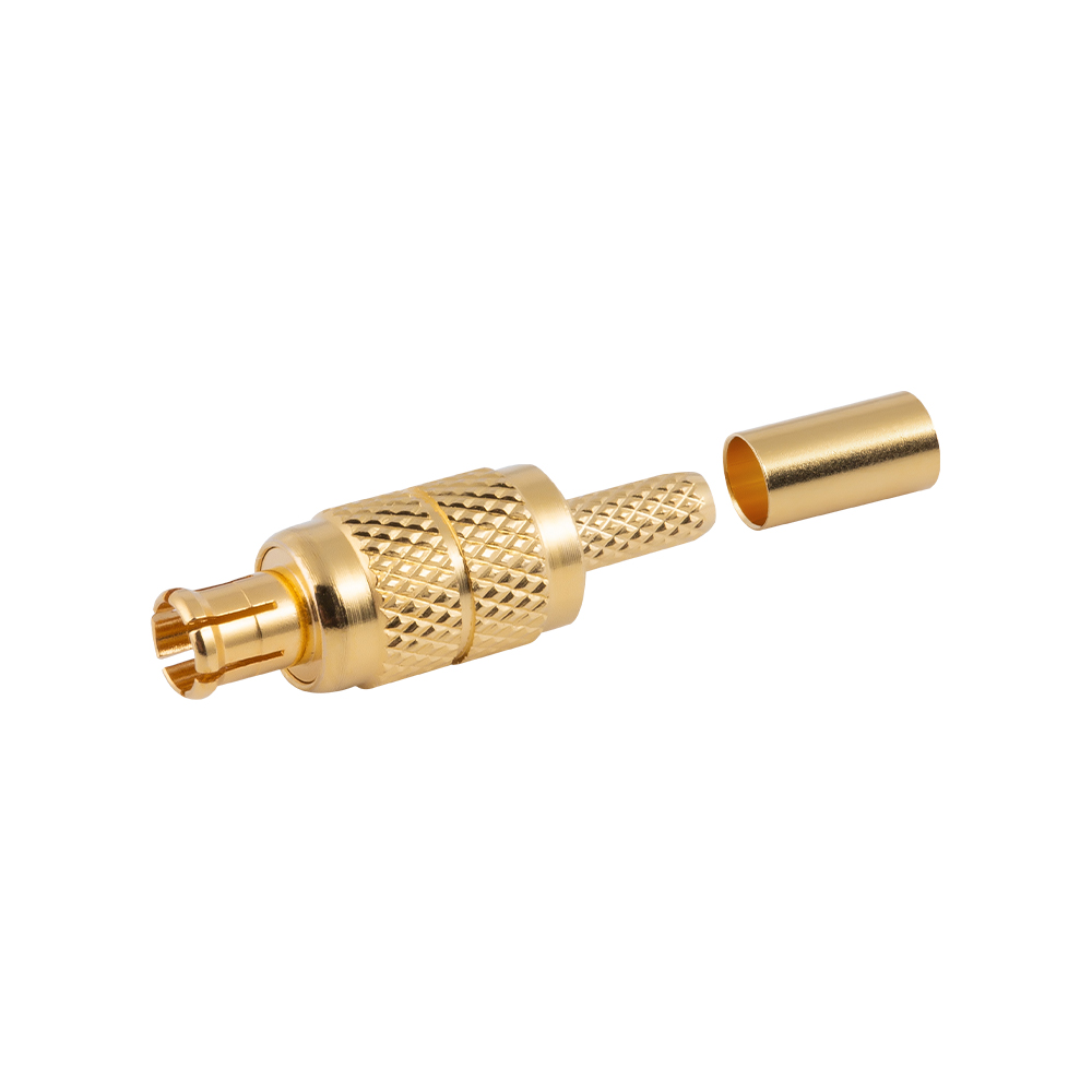
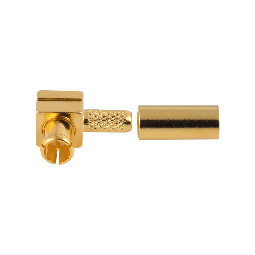
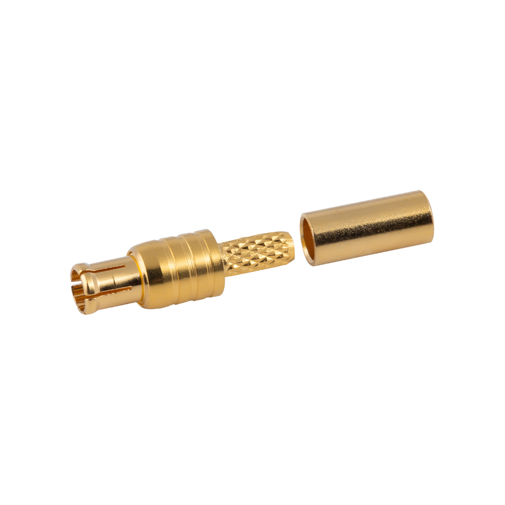
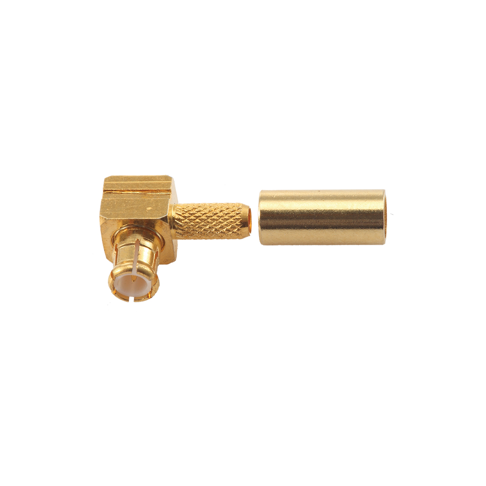
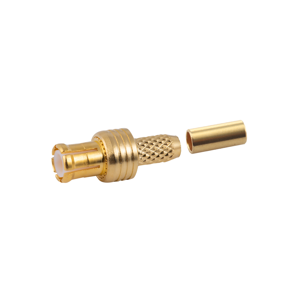
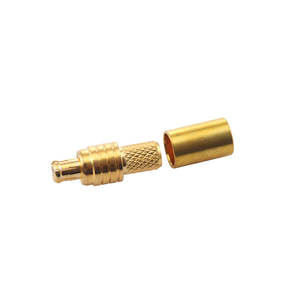
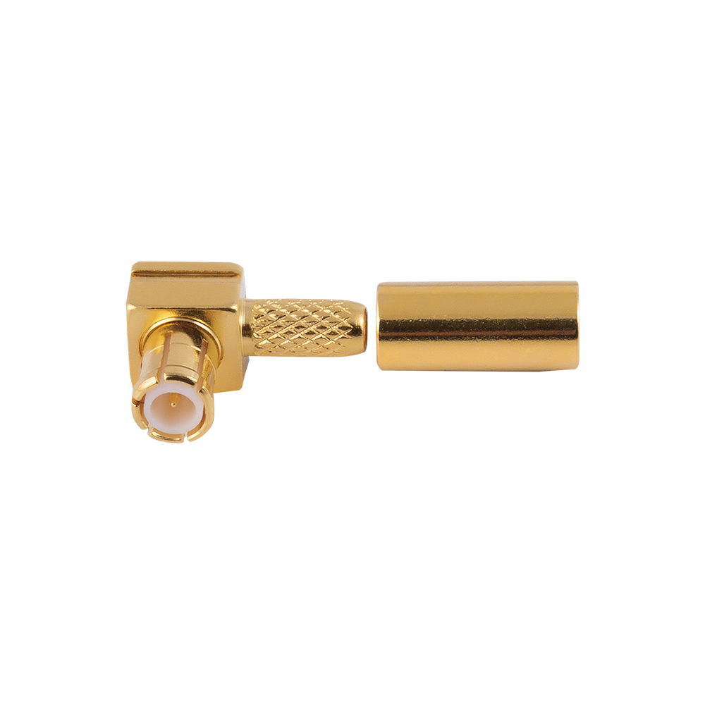
| MCX / MMCX | 50 ohm | Up to 6 GHz | Micro-coax | Compact PCB-to-antenna links |
| 7-16 DIN | 50 ohm | Up to 7.5 GHz | Large-diameter feeders | Base stations, high power |
When the cable run feeds an outdoor antenna, N type RF coaxial connectors provide weather-resistant construction and stable electrical performance across the cellular and Wi-Fi bands. For compact RF modules and test ports, SMA RF coaxial connectors remain the default interface up to 18 GHz. And for base station transmitters, 7-16 DIN RF coaxial connectors keep insertion loss and intermodulation low at high power levels.
 Wholesale 7/16(L29) RF Coaxial Connectors Manufacturer, FactoryYangzhou Jingcheng Electronics Co., Ltd. is China 7/16(L29) RF Coaxial Connectors manufacturer and 7/16(L29) RF Coaxial Connectors factor...View Product →
 Wholesale SMA RF Coaxial Connectors Manufacturer, FactoryYangzhou Jingcheng Electronics Co., Ltd. is China SMA RF Coaxial Connectors manufacturer and SMA RF Coaxial Connectors factory, we offeri...View Product →
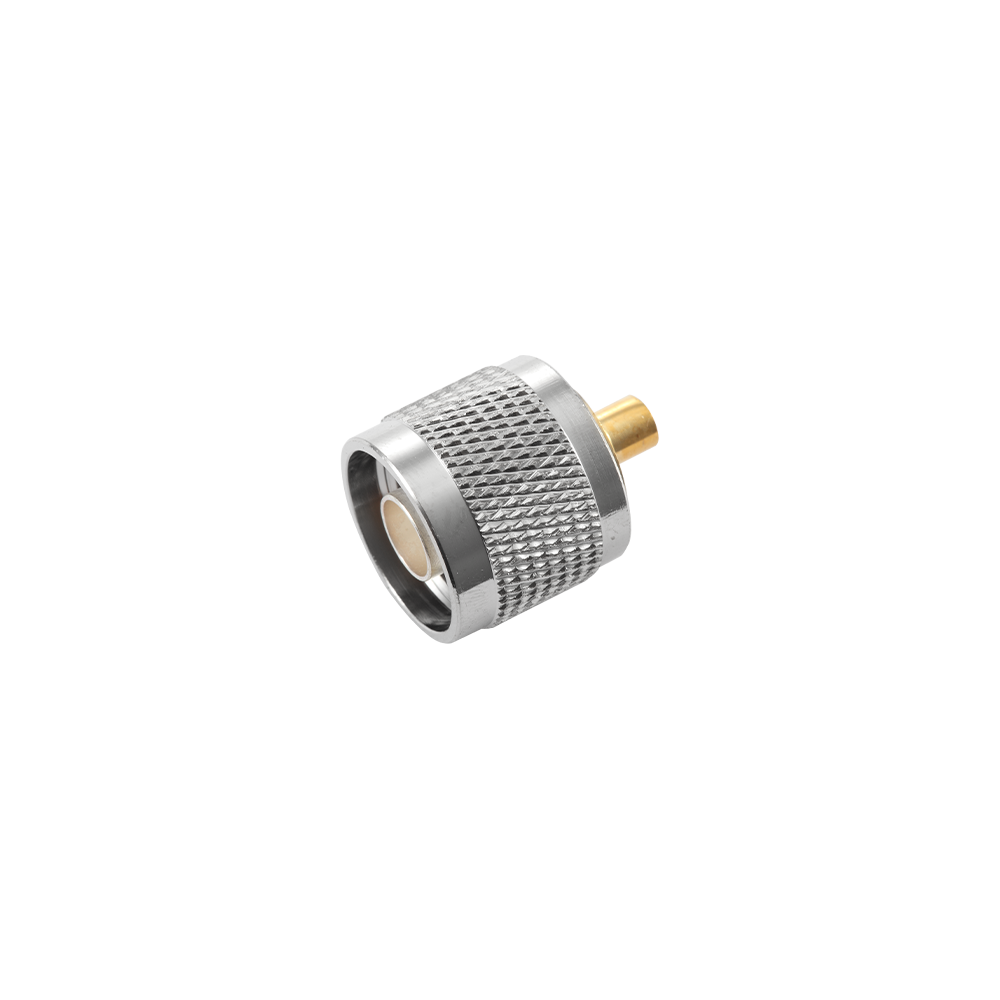 Wholesale N RF Coaxial Connectors Manufacturer, FactoryYangzhou Jingcheng Electronics Co., Ltd. is China N RF Coaxial Connectors manufacturer and N RF Coaxial Connectors factory, we offering w...View Product →
Shielding and Dielectric Choice Affect Noise Immunity and Stability
Shielding determines how much external noise reaches the inner conductor and how much signal leaks out; in crowded environments or high-speed data paths, use double-shielded or foil-plus-braid constructions rather than single braid. A foil layer blocks high-frequency noise while a braided layer provides mechanical strength and low-resistance grounding.
The dielectric is just as important: solid polyethylene is economical but lossier at microwave frequencies, while foam or PTFE dielectrics lower attenuation at higher cost. Foam dielectric is lighter and more flexible but more sensitive to crushing and moisture, so reserve it for indoor runs and choose solid dielectric for outdoor or high-vibration paths.
Application-Based Selection Summary
The fastest way to select a cable is to start from the installation environment and let RF requirements narrow the cable and connector family: long outdoor runs prioritize attenuation and weather sealing, module-level wiring prioritizes size and flexibility, and test setups prioritize repeatable impedance and stable connector torque.
Base station feeder
Use 7-16 DIN or N connectors with a low-loss foam-dielectric cable; verify intermodulation performance.
Test and measurement
Use SMA connectors with semi-rigid cable, and check VSWR stability under repeated flexing and torque.
IoT and portable devices
Use MMCX or MCX with micro-coax to save board space and allow a light, flexible antenna pigtail.
CCTV and video
Use RG-59 or RG-6 with BNC connectors, keeping the system at 75 ohm to avoid visible signal artifacts.
Outdoor antenna feed
Use N connectors with a double-shielded flexible cable and a weatherproofed joint at the antenna.
Microwave board interconnect
Use SMP or 2.92 mm connectors with semi-rigid cable to control performance above 10 GHz.
Practical Purchasing Considerations for Production
For volume orders, verify mechanical tolerances, plating quality, and lot-to-lot impedance consistency rather than relying only on the datasheet; a connector that works on a prototype bench can fail in the field if the cable center conductor diameter sits at the edge of the connector crimp range. Ask your supplier for mating dimension checks, cable retention force, and environmental documentation.
A dedicated RF connector manufacturer with a broad catalog can also reduce your vendor count, especially when interconnections become complex. A small, clearly identified set of intertype RF adapters covers unusual transitions during bring-up and test, so you do not need to re-cable a working setup for a single measurement.
Coaxial Cable Selection FAQ
Can I use a 75 ohm cable in a 50 ohm system?
Short temporary jumpers work, but the mismatch adds return loss and can create ripple in tight-bandwidth systems. Avoid this combination for production or for any link that requires stable VSWR.
What is the difference between RG-6 and RG-59?
RG-6 has a larger conductor and lower attenuation, making it a better choice for satellite, long cable runs, and high-frequency video; RG-59 is thinner, cheaper, and still adequate for short CCTV links.
Which connector is best for outdoor use?
N type connectors are the usual outdoor standard for RF because of their sealed construction and stable performance; TNC is also suitable when vibration is a concern. Confirm the specific connector has an IP-rated or weatherized version.
How do I match a connector to my cable?
Check the connector datasheet for the supported cable diameter and dielectric outer diameter, not just the series name such as SMA or N. The cable and connector must share the same impedance and the connector must suit the cable’s outer jacket size.
Does cable length affect impedance?
No. Impedance is a per-unit property of the cable construction. Length affects total attenuation, phase, and DC resistance, but it does not change the nominal characteristic impedance.
Final Selection Checklist
Before approving a sample for production, run through these checks:
- Confirm system impedance is 50 or 75 ohm and the cable matches.
- Verify attenuation and power handling at the highest operating frequency.
- Match connector series to cable diameter and frequency range.
- Select shielding for the noise environment and double-check leakage requirements.
- Consider jacket material, temperature rating, and bend radius for outdoor or flexing installs.
- Validate connector torque, crimp tooling, and lot-to-lot consistency with the actual cable.
A coaxial cable is rarely the most expensive part of an RF system, yet it is one of the most common sources of field rework. Choosing impedance, cable class, and connector family carefully on the first pass saves test time, assembly rework, and final test failures.