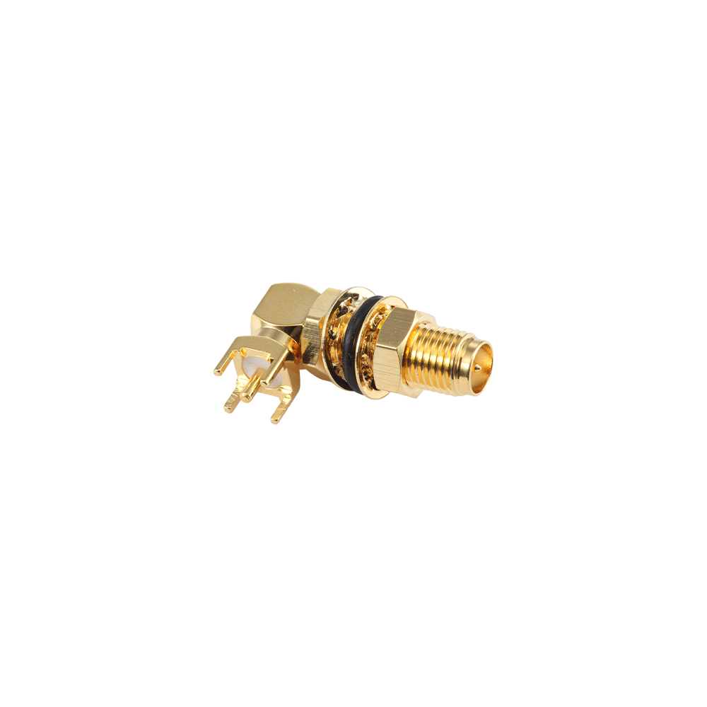
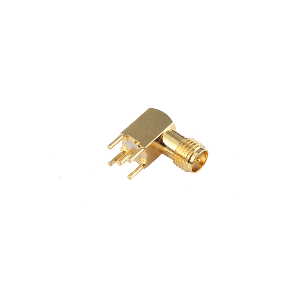
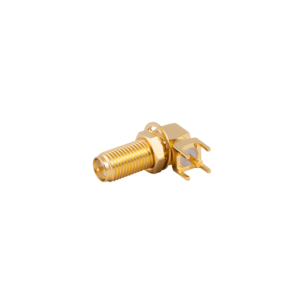
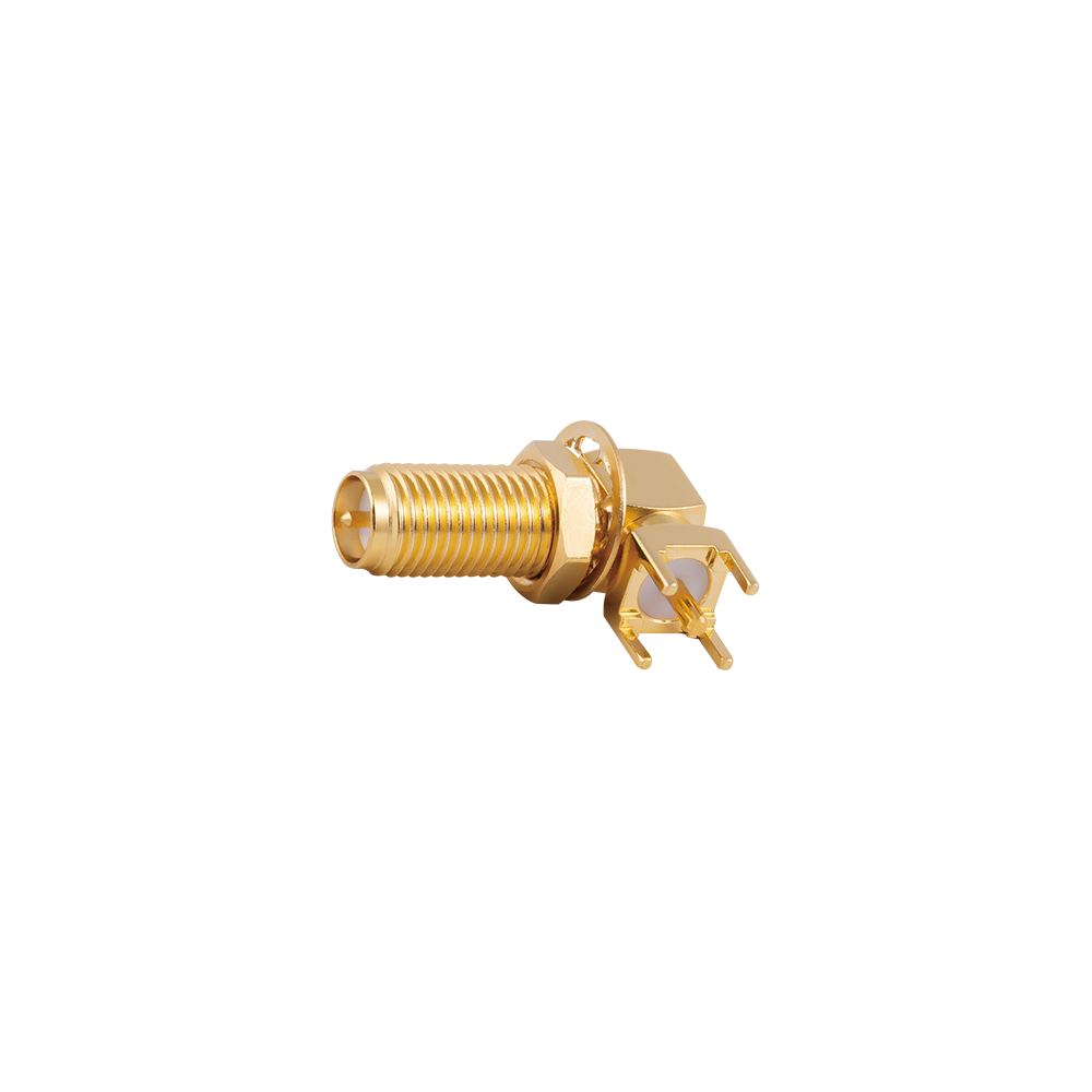
RPSMA PCB Connectors Custom

Home / Products / Reverse Polarity Connectors / RPSMA Reverse Polarity Connectors / RPSMA PCB Connectors

RPSMA PCB Connectors Manufacturer

Product Overview
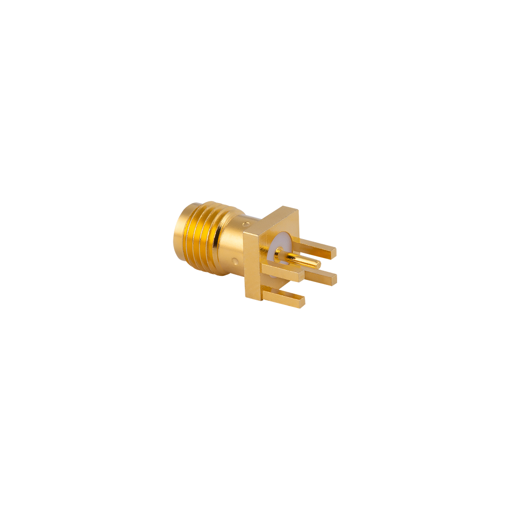
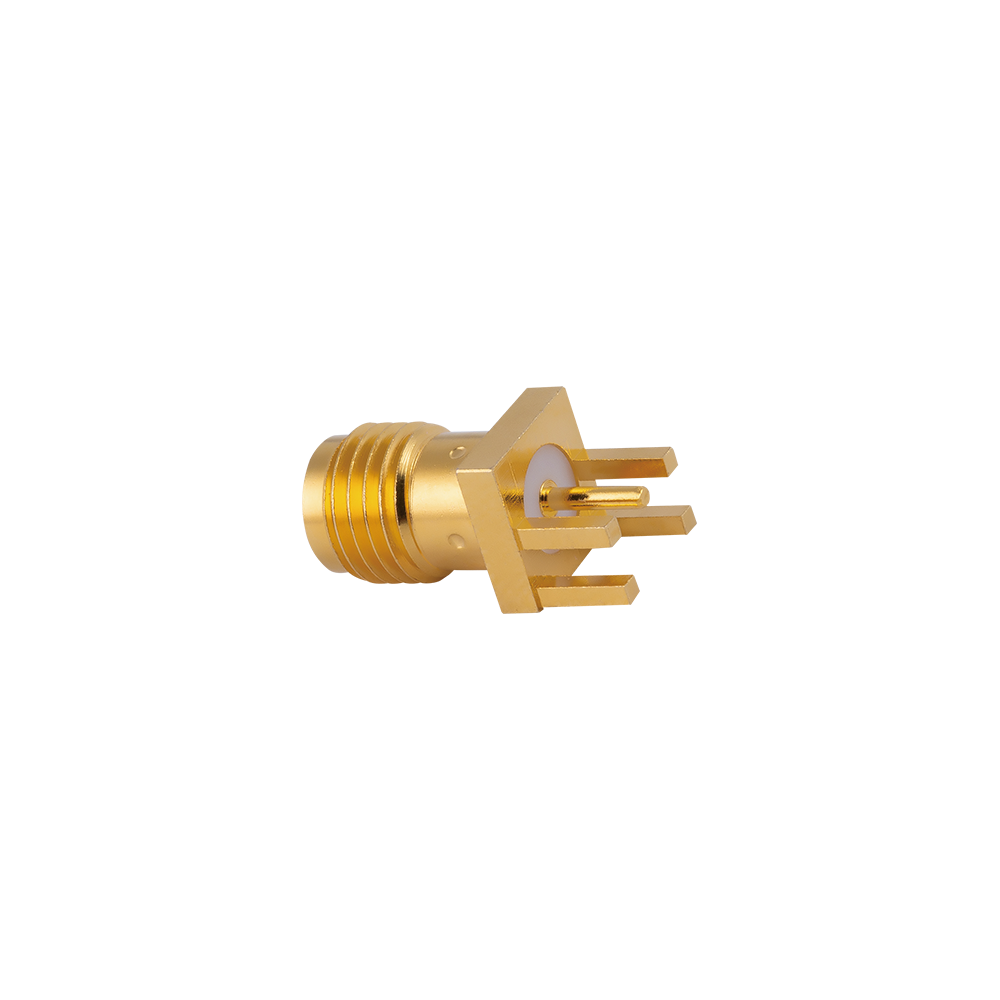
The RPSMA PCB connector mounts onto the circuit board and presents the RP-SMA mating interface at the board edge or through a panel cutout, allowing external RPSMA antenna cables to connect directly to the PCB RF circuitry — the standard solution for consumer Wi-Fi router motherboards, WLAN access point boards, and IoT gateway PCBs where a panel-mount RP-SMA port is required without a pigtail cable intermediate.

Key Features
Through-hole PCB mounting with robust solder retention for resistance to the mating and unmating forces of repeated antenna cable connection
Reversed center conductor (RP) interface for universal compatibility with all RPSMA-standard external antenna cables
Precision center pin height and PCB alignment geometry for consistent 50 Ω impedance at the board-to-connector transition
50 Ω matched impedance and low insertion loss across 2.4 GHz, 5 GHz, and 6 GHz Wi-Fi frequency bands
Compact PCB footprint supporting high-density Wi-Fi device board designs
Compatible with standard wave-solder PCB assembly processes for cost-effective volume production
Gold-plated center contact ensuring reliable solderability and long-term contact stability
RoHS-compliant; suitable for global consumer electronics supply chains

Typical Applications
Consumer Wi-Fi router and access point mainboard external antenna port connector
WLAN repeater and range extender PCB antenna connection point
IoT gateway and smart home hub PCB external antenna port
Industrial WLAN equipment PCB RF panel connector
Wireless display and multimedia streaming device PCB antenna port

FAQ
Q: Can RPSMA PCB connectors be used on both single-sided and double-sided PCBs?
A: Yes — our through-hole RPSMA PCB connectors are compatible with single-sided, double-sided, and multi-layer PCB constructions; the through-hole solder attachment provides reliable retention regardless of PCB layer count.
Q: What is the difference between an RPSMA PCB connector and an RPSMA micro-strip connector?
A: The RPSMA PCB connector provides a panel-accessible port with robust through-hole mechanical retention for repeated cable mating, while the RPSMA micro-strip connector is optimized for the PCB trace-to-coax RF transition with minimal insertion loss and is typically not intended for repeated field mating cycles.
About
Yangzhou Jingcheng Electronics Co., Ltd.

Yangzhou Jingcheng Electronics Co., Ltd., a premier China RPSMA PCB Connectors Manufacturer and RPSMA PCB Connectors Supplier, was founded in 1999. It is a high-tech enterprise specializing in the R&D and manufacturing of RF coaxial connectors, cable assemblies, and passive microwave components.
Equipped with a comprehensive R&D and production system, the company has obtained international certifications including ISO9001. Adhering strictly to standards such as MIL, IEC and GB, we offer over 30 product series with more than 2,000 specifications, covering SMA, BNC, N-type and other mainstream models. Our products are widely applied in the fields of communications, aerospace, automotive electronics and beyond, and exported to many countries and regions across Europe, America and Asia.
We uphold the tenet of "Quality as the Foundation, Customers as the Core", committed to providing reliable interconnection solutions and professional services for global clients.

News & Updates
50 Ohm Coax Cable Explained: What It Means, Why It Matters, and How to Choose
Industry News
2026-09-11
50 Ohm Coax Cable Explained: What It Means, Why It Matters, and How to Choose
A 50 ohm coax cable is a transmission line with a characteristic impedance of 50 ohms, and it is the default choice in most RF systems because it balances low signal loss with reasonable power-handling capability. The “50 ohm” rating does...
12G BNC Connector Guide: 75-Ohm Coaxial Connectors for 4K and 8K SDI Video Systems
Industry News
2026-09-04
12G BNC Connector Guide: 75-Ohm Coaxial Connectors for 4K and 8K SDI Video Systems
A 12G BNC connector is a 75-ohm RF coaxial connector engineered to carry 12G-SDI signals up to 12 Gbps, supporting 4K and 8K video over a single cable. It is not merely a "standard BNC" with a different part number; its electrical perform...
Antenna Connector Types: SMA vs N Type vs TNC vs BNC vs RP-SMA Complete Guide
Industry News
2026-08-24
Antenna Connector Types: SMA vs N Type vs TNC vs BNC vs RP-SMA Complete Guide
Choosing an antenna connector is one of those small decisions that can make or break an RF installation. Get it right, and the system performs almost invisibly; get it wrong, and you lose signal before power even reaches the antenna. For ...
Coaxial Cable Selection Guide: Choosing Cable, Connectors, and RF Performance
Industry News
2026-08-21
Coaxial Cable Selection Guide: Choosing Cable, Connectors, and RF Performance
An RF engineer once told me that most field failures are not component failures; they are selection failures. Selecting a coaxial cable starts with three decisions: characteristic impedance, cable size, and connector family. Get these thr...
Coax Cable Comparison: RG58 vs RG59 vs RG6 vs RG11 and Connector Matching
Industry News
2026-08-14
Coax Cable Comparison: RG58 vs RG59 vs RG6 vs RG11 and Connector Matching
Choosing a coaxial cable without comparing impedance, attenuation, and connector compatibility usually ends in poor signal quality. The practical rule is short: 50 Ω cables such as RG58 are for radio equipment, test instruments, and compac...
RPSMA PCB Connectors Industry knowledge

An RPSMA PCB connector is a Reverse Polarity SMA connector designed for direct mounting onto a printed circuit board, rather than for termination onto a length of cable. The center contact position is reversed compared to a standard SMA connector, while the outer threaded coupling remains unchanged, so the connector body threads onto standard SMA mating hardware but does not form a signal path with a standard SMA center contact. As a manufacturer of RF coaxial connectors since 1999, Yangzhou Jingcheng Electronics Co., Ltd (JC Company) produces RPSMA PCB connectors in several mounting styles for use on RF and wireless circuit boards.

Reverse Polarity Design Principle

In a standard SMA connector, the plug carries the center pin and the jack carries the center socket. In an RPSMA connector, this arrangement is reversed: the RPSMA plug contains a center socket, and the RPSMA jack contains a center pin. This reversal applies equally to PCB-mount versions, meaning the PCB footprint and center contact geometry of an RPSMA PCB connector differ from those of a standard SMA PCB connector even though the outer body and thread dimensions are compatible.

Mounting Types

RPSMA PCB connectors are produced in several mounting configurations, selected according to the board layout and mechanical requirement of the assembly.

Mounting Type Description Typical Application
Edge mount Connector body is positioned at the board edge, with the center contact soldered to the board trace along the edge Boards with an accessible edge for connector placement
End launch Connector is mounted at the end of the board with the center contact aligned to the board microstrip or stripline RF boards requiring a controlled impedance transition at the board edge
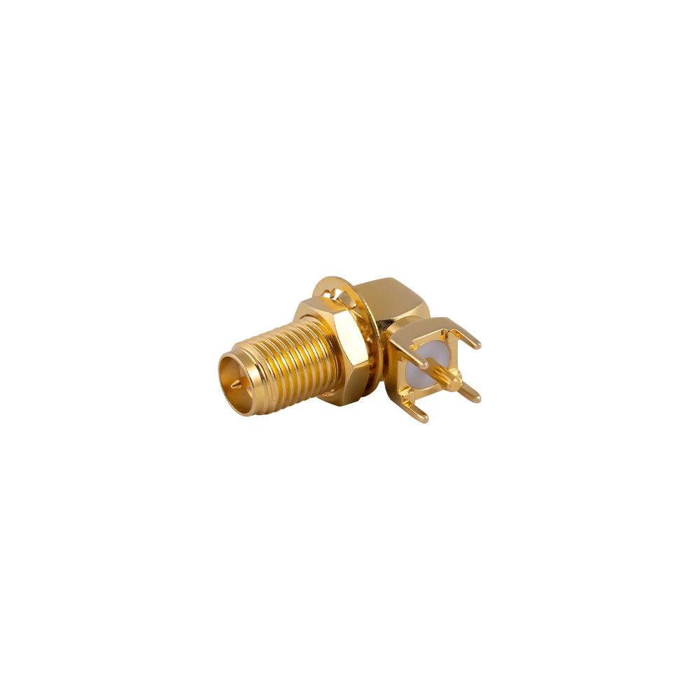
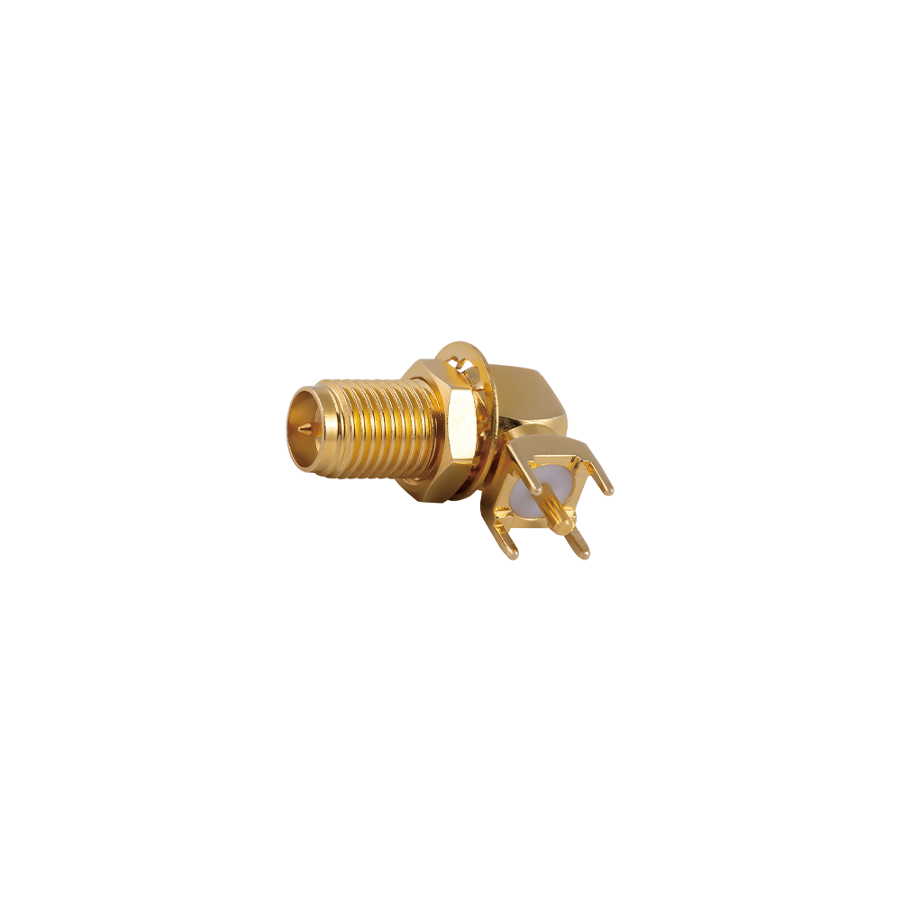
Through-hole Connector pins pass through plated holes in the board and are soldered on the opposite side General purpose board mounting where vertical connector placement is acceptable
Surface mount (SMT) Connector is reflow soldered directly onto board pads without through-hole pins Automated assembly processes and space-constrained board layouts

Panel and Bulkhead PCB Variants

In addition to direct board mounting, some RPSMA PCB connectors are supplied with a bulkhead or panel-mount body, allowing the connector to be fixed through an enclosure wall while the rear contact is connected to the board through a short internal cable or a direct board interface. This configuration is used where the connector must be externally accessible while remaining electrically connected to internal circuitry.

Typical Applications

RPSMA PCB connectors are used on circuit boards within RF and wireless systems that require a reverse polarity interface, including:

  • Wi-Fi and wireless local area network (WLAN) modules
  • Router and access point main boards with external antenna ports
  • Machine-to-machine (M2M) and IoT communication boards
  • Test fixtures and evaluation boards requiring a reverse polarity connection point

Key Technical Parameters

Parameter General Reference Range
Impedance 50 ohm
Frequency range DC to several GHz, depending on connector series and board transition design
Mating cycles Rated according to threaded coupling design, typically several hundred cycles
Mounting process Wave solder, hand solder, or reflow solder, depending on mounting type
Contact materials Brass or beryllium copper body with gold or other plating on contact areas

Selection Considerations

When selecting an RPSMA PCB connector, the following factors are typically reviewed:

  • Board thickness and edge accessibility, to determine edge mount or end launch suitability
  • Assembly process used, such as wave soldering, hand soldering, or reflow, to determine through-hole or surface mount selection
  • Required plug or jack polarity based on the mating cable or equipment interface
  • Operating frequency range and impedance matching requirement of the RF trace
  • Mechanical retention requirement, including whether the connector will experience repeated mating cycles

Frequently Asked Questions

What is the difference between RPSMA and standard SMA PCB connectors?

The outer thread coupling is the same, but the center contact position is reversed. This means the board footprint and mating behavior differ from a standard SMA PCB connector, even though both use the same thread interface.

Can an RPSMA PCB connector be soldered using an automated process?

Through-hole and surface mount RPSMA PCB connectors can generally be processed using wave soldering or reflow soldering, depending on the specific connector design and the assembly equipment used.

Is edge mount or end launch better for RF performance?

End launch designs are generally used where a controlled impedance transition to the board trace is required, while edge mount designs are used where board space and layout constraints take priority. The appropriate choice depends on the specific board design and frequency requirement.