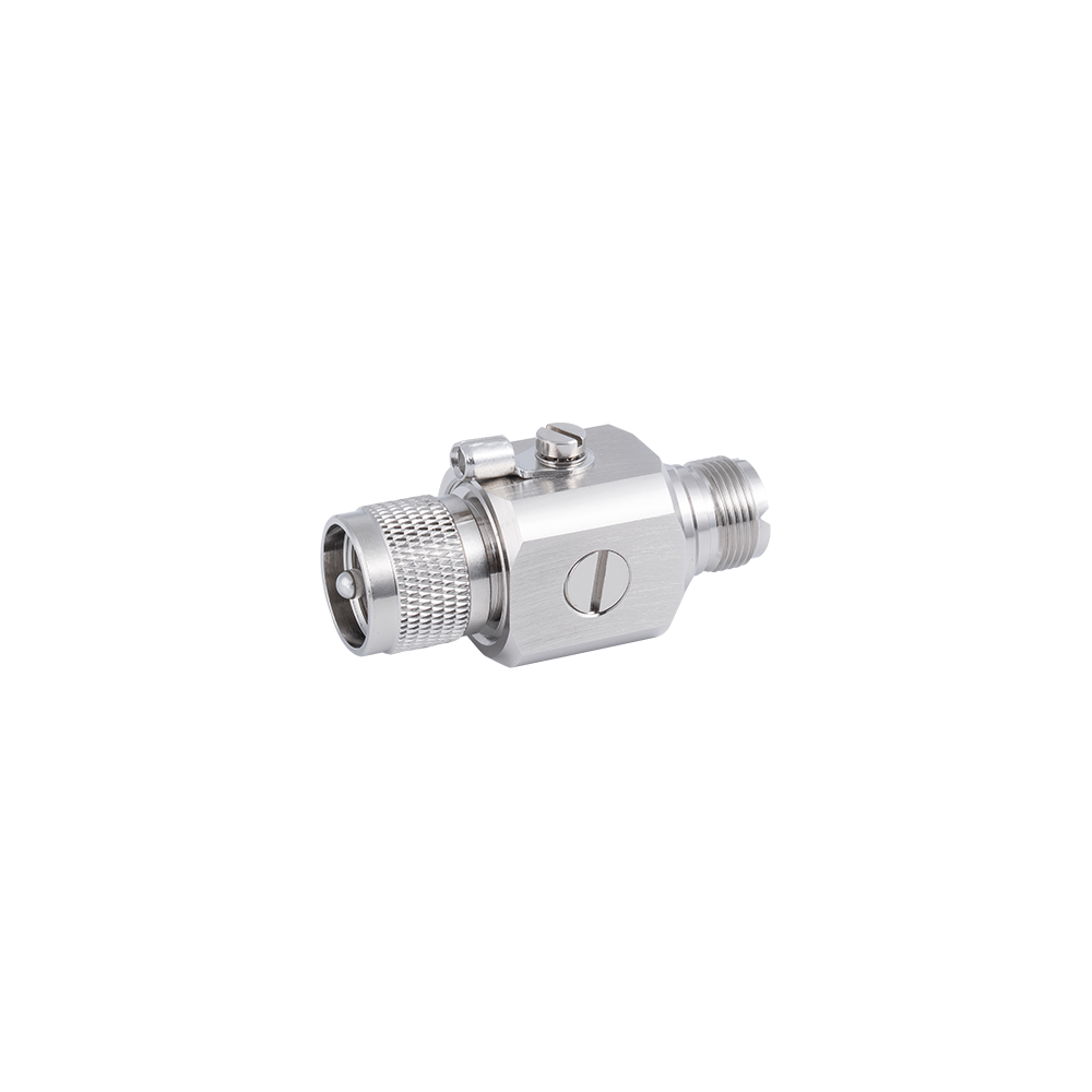
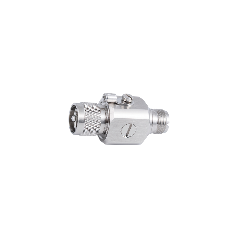
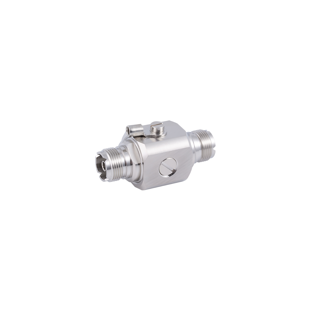
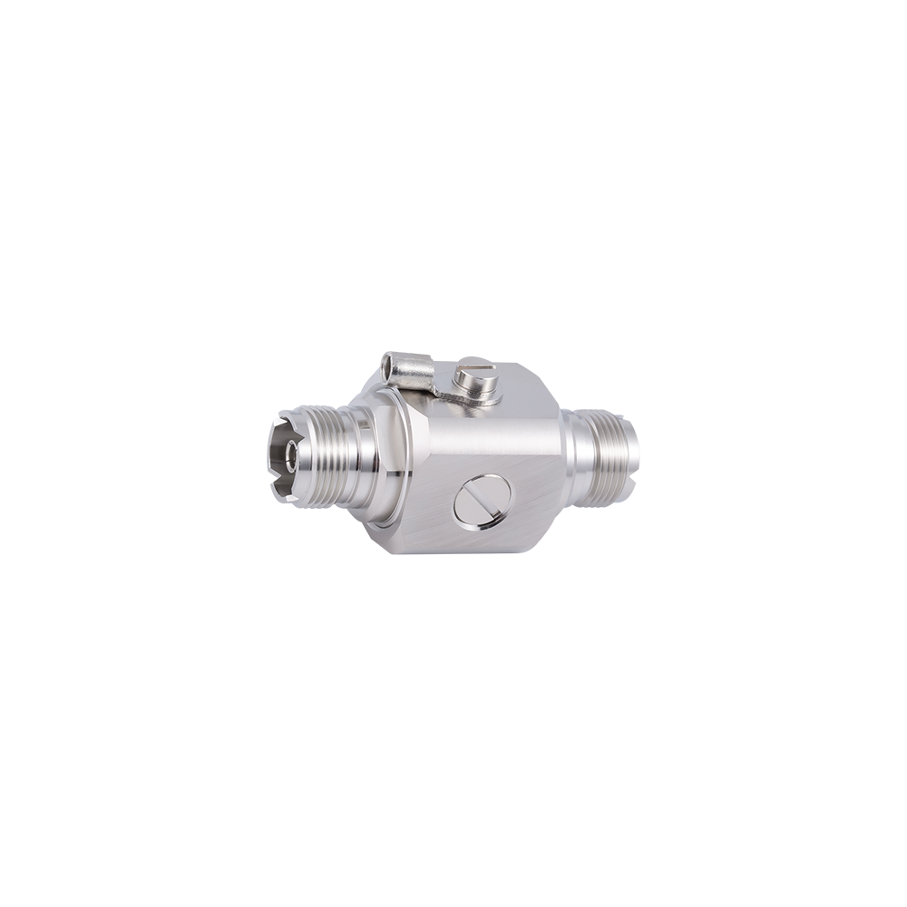
Product Overview This UHF coaxial surge protector is engineered for the UHF connector series (including PL-259 plugs and SO-239 jacks) utilized in amateur radio, citizens band (CB) radio, and private wireless radio base stations. Optimized for operation below 300 MHz, the UHF interface format features a large physical envelope, high power-handling capability, and straightforward field assembly for HF and low-VHF antenna systems. The protector integrates a gas discharge tube (GDT) transient suppression element within a heavy-duty UHF mechanical housing, providing surge protection for antenna systems feeding HF transceivers, linear power amplifiers, and VHF base station equipment.
Key Features UHF SO-239 female-to-female or PL-259 compatible inline configuration for standard UHF antenna coaxial runs Protection frequency range from DC to 300 MHz optimised for HF and VHF UHF-connector applications High peak surge current GDT for lightning environments typical of elevated HF antenna systems Large-body heavy-duty construction matching the robust mechanical nature of the UHF connector series Suitable for RG-58, RG-8, RG-213, and LMR-400 equivalent coaxial cables commonly used with UHF connectors Grounding lug for compliance with antenna system earthing requirements Nickel or silver-plated brass body for long service life in station equipment room and outdoor pedestal applications Low insertion loss at HF and VHF frequencies to preserve transmitter output power and receiver sensitivity
Typical Applications Amateur radio HF transceiver and linear amplifier antenna port protection VHF/UHF base station antenna coaxial run surge protection CB radio base station antenna feed protection Land-mobile radio (LMR) repeater and base station coaxial antenna connections
FAQ Q: What frequency range does the UHF protector support? A: The unit is optimised for DC to 300 MHz covering the HF and VHF bands where UHF-series connectors are typically used; it is not intended for microwave applications. Q: Can it handle the output of a high-power HF linear amplifier? A: Power handling depends on the specific variant; please provide your transmitter output power level for confirmation that the appropriate variant is recommended. Q: Is it suitable for unattended remote base station installations? A: Yes—the robust GDT and weatherproof construction variants are well-suited for unattended remote sites where reliable long-term protection without maintenance is required. Q: What cable types are compatible? A: Compatible with RG-58, RG-8X, RG-213, RG-8, and LMR-400 equivalent cables when assembled with standard PL-259 plugs; the protector connects between assembled PL-259 plugs and the equipment SO-239 socket.
Yangzhou Jingcheng Electronics Co., Ltd., a premier China UHF Coaxial Lightning Protector Manufacturer and UHF Coaxial Lightning Protector Factory, was founded in 1999. It is a high-tech enterprise specializing in the R&D and manufacturing of RF coaxial connectors, cable assemblies, and passive microwave components.
Equipped with a comprehensive R&D and production system, the company has obtained international certifications including ISO9001. Adhering strictly to standards such as MIL, IEC and GB, we offer over 30 product series with more than 2,000 specifications, covering SMA, BNC, N-type and other mainstream models. Our products are widely applied in the fields of communications, aerospace, automotive electronics and beyond, and exported to many countries and regions across Europe, America and Asia.
We uphold the tenet of "Quality as the Foundation, Customers as the Core", committed to providing reliable interconnection solutions and professional services for global clients.
UHF Coaxial Lightning Protector Industry knowledge
1. Introduction to UHF Connector‑Based Lightning Protection
The UHF connector family—comprising PL‑259 plugs and SO‑239 jacks—has served as the de‑facto standard for HF and low‑VHF RF connections in amateur radio, citizens band (CB) radio, and land‑mobile radio (LMR) base stations for decades. These connectors are characterised by their large physical size, robust mechanical construction, and ability to handle substantial RF power, typically up to several hundred watts or more in the HF region. However, the same elevated antenna systems that provide excellent communication range also present a direct path for lightning‑induced transients, which can couple into the coaxial feed line and damage sensitive transceiver front‑ends, power amplifiers, and associated equipment. A UHF Coaxial Lightning Protector addresses this vulnerability by inserting a gas discharge tube (GDT) surge‑suppression element directly in the signal path, diverting surge energy to ground while maintaining normal RF transmission.
Yangzhou Jingcheng Electronics Co., Ltd., with its extensive background in RF connector manufacturing since 1999, offers a dedicated UHF Coaxial Lightning Protector that matches the mechanical and electrical characteristics of the UHF interface. The company’s ISO9001‑certified production processes and compliance with MIL, IEC, and GB standards ensure that each protector meets the ruggedness and reliability expectations of amateur radio operators and commercial LMR system integrators. Unlike miniature connector protectors designed for microwave frequencies, the UHF protector is optimised for the DC‑300 MHz spectrum, where low insertion loss and high surge‑current handling are the primary performance drivers. This article provides a technically grounded examination of the design, performance, and practical application of these protectors, supported by data visualisations that clarify key trade‑offs.
2. Fundamental Operating Principle and Protection Element
(1) Gas Discharge Tube (GDT) Technology – The core of the UHF Coaxial Lightning Protector is a hermetically sealed gas‑filled tube with two electrodes. Under normal signal‑level voltages (typically below 90 V), the gas remains non‑conductive, and the tube presents a very high impedance, allowing the RF signal to pass with negligible attenuation. When a voltage surge exceeding the spark‑over threshold (typically 90 V to 470 V, depending on the specified protection level) appears across the line, the gas ionises and becomes a low‑impedance plasma channel, effectively shorting the surge to the ground terminal. This action occurs within microseconds, limiting the voltage that reaches the protected equipment to a safe level. After the surge decays, the gas de‑ionises and the protector returns to its transparent state, ready for subsequent events.
(2) Comparison with Alternative Suppression Technologies – While metal‑oxide varistors (MOVs) and transient‑voltage‑suppression (TVS) diodes are also used for surge protection, GDTs offer distinct advantages for HF/VHF applications. MOVs have higher capacitance (typically tens to hundreds of pF), which can introduce significant insertion loss above 30 MHz and degrade VSWR. TVS diodes exhibit even higher capacitance and are generally limited in surge‑current capability. The GDT used in the UHF Coaxial Lightning Protector exhibits a capacitance of less than 1 pF, ensuring that insertion loss remains below 0.2 dB across the entire DC‑300 MHz range. Furthermore, GDTs can handle surge currents of 10 kA to 20 kA (8/20 μs waveform) with a single event, and they provide multiple‑strike capability—typically 10 strikes at 5 kA—which is essential for unattended remote base stations that may experience repeated nearby lightning activity.
(3) Frequency‑Selective Considerations – Some protectors employ quarter‑wave stub or band‑pass filter structures to achieve low residual voltage, but these are inherently narrowband and do not pass DC, making them unsuitable for applications that require remote antenna switching or bias‑tee powering. The GDT‑based UHF Coaxial Lightning Protector preserves DC continuity, allowing the passage of DC control voltages or low‑current bias for preamplifiers, while still providing effective surge suppression. This feature is particularly valuable in amateur radio setups where antenna switching or receive preamplifiers are powered through the coaxial cable.
Table 1: Comparison of GDT with MOV and TVS for UHF Protectors
Parameter
GDT
MOV
TVS Diode
Capacitance
< 1 pF
100 - 1000 pF
50 - 500 pF
Max Surge Current (8/20 μs)
10 - 20 kA
2 - 10 kA
0.5 - 3 kA
DC Pass
Yes
Yes
Yes
Lifetime (surges)
> 400 events
Limited
Limited
Suitability for HF/VHF
Excellent
Moderate
Poor
The table above clearly illustrates why GDT is the preferred technology for UHF‑connector protectors. The combination of ultra‑low capacitance, high surge‑current rating, and long operational life aligns with the demands of HF/VHF systems where signal integrity and robustness are paramount. Yangzhou Jingcheng Electronics selects GDT elements that have been characterised for consistent spark‑over voltage and low insertion loss, ensuring that the UHF Coaxial Lightning Protector delivers dependable performance over years of service in both equipment rooms and outdoor pedestal installations.
3. Frequency‑Dependent Performance: Insertion Loss and VSWR
For any coaxial protector, insertion loss and voltage standing wave ratio (VSWR) are the primary figures of merit that determine the impact on transmitted and received signals. The UHF Coaxial Lightning Protector is designed to introduce negligible degradation across its intended operating range of DC to 300 MHz. The following line chart presents typical insertion loss measured from 1 MHz through 300 MHz for a representative production unit.
The chart employs a logarithmic frequency scale to better visualise the behaviour across the wide HF range (1.8 – 30 MHz) and into the VHF low band (50 – 300 MHz). The blue curve represents the measured insertion loss in decibels, while the red dashed line indicates the 0.2 dB reference level that is commonly considered acceptable for HF/VHF systems. Observations from the chart show that loss remains below 0.05 dB through most of the HF spectrum, rising gradually above 100 MHz to reach approximately 0.15 dB at 300 MHz. This performance is achieved through careful impedance matching of the internal GDT structure and the use of low‑loss dielectric materials in the connector body.
VSWR measurements, not shown graphically, typically remain below 1.15:1 across the entire band, which translates to a return loss of better than 23 dB. Such low reflections ensure that nearly all transmitter power is delivered to the antenna, and that receiver noise figure is not degraded by mismatch losses. This is particularly important for weak‑signal amateur radio modes like FT8 or CW, where every decibel of loss can reduce the effective communication range. The stable impedance characteristics also benefit linear amplifiers by presenting a consistent load impedance, helping to maintain linearity and efficiency.
The chart confirms that the UHF Coaxial Lightning Protector introduces less than 0.2 dB of loss up to 300 MHz, which is well within the acceptable range for most amateur and commercial HF/VHF installations. In practice, this loss is comparable to the attenuation introduced by a few additional feet of RG‑8 coaxial cable, and it is often indistinguishable from the normal system variation. The flatness of the curve, with minimal ripples, indicates that the impedance match is consistent across the band, avoiding the resonances that can occur with poorly designed internal structures. This performance is achieved by employing a precision‑machined brass body with a controlled inner conductor geometry, combined with a GDT that has been specifically selected for low capacitance and stable RF characteristics. Yangzhou Jingcheng Electronics performs 100% swept‑frequency testing on every production unit to verify that each protector meets the published insertion‑loss and VSWR specifications. Users can therefore deploy the protector without needing to re‑tune their antenna systems or adjust their amplifier matching networks. The low loss also ensures that receiver preamplifiers do not experience unnecessary gain reduction, maintaining the signal‑to‑noise ratio essential for weak‑signal work. This combination of measured performance and manufacturing consistency makes the UHF Coaxial Lightning Protector a reliable component in any HF/VHF signal chain.
4. Surge Current and Peak Power Handling Capability
Beyond RF performance, the primary function of any lightning protector is to safely divert surge energy. The UHF Coaxial Lightning Protector is rated for a maximum discharge current of 20 kA (8/20 μs waveform) for a single event, and 10 kA for multiple events over its lifetime. The following bar chart illustrates the relationship between surge current level and the resulting residual voltage (let‑through voltage) that appears at the protected equipment port.
The chart is based on typical characterisation data for the GDT used in the protector, measured with a standard 8/20 μs impulse current generator. The x‑axis shows the injected surge current in kiloamperes, while the y‑axis shows the corresponding residual voltage in volts. Three current levels are shown: 5 kA, 10 kA, and 20 kA. At 5 kA, the residual voltage is approximately 500 V; at 10 kA, it rises to about 700 V; and at 20 kA, it reaches around 1 kV. These values represent the clamping voltage that the protector allows to pass to the equipment; the actual damage threshold of modern solid‑state transceivers is typically much higher (often > 100 V for short pulses), but the protector’s fast response time limits the energy delivered.
It is important to note that the residual voltage increases with surge current, but the total energy (proportional to the integral of voltage × current × time) is still significantly reduced compared to the unprotected case, where the full surge voltage (potentially tens of kilovolts) would appear across the equipment input. The protector’s spark‑over voltage is factory‑set to a nominal value (e.g., 230 V) for standard models, with optional low‑voltage (90 V) or high‑voltage (470 V) versions available for specialised applications such as those with high standing DC voltages. The power‑handling capability of the protector itself (in terms of RF power) is separate from its surge rating; RF power handling is determined by the conductor size and dielectric strength, and the UHF Coaxial Lightning Protector is designed to handle up to 500 W average RF power in the HF band, and up to 300 W in the VHF band, without degradation.
The bar chart illustrates a clear trend: as the surge current increases, the residual voltage also rises, which is expected due to the finite impedance of the ionised gas plasma. However, even at the maximum rated 20 kA, the residual voltage of about 1 kV is still far below the typical withstand voltage of many vacuum‑tube amplifiers (which can tolerate several kilovolts) and is within the safe operating area of most modern transceivers, which incorporate internal over‑voltage protection on their antenna inputs. For installations with particularly sensitive equipment, such as low‑noise receive converters, a hybrid protector (GDT plus TVS) can further reduce the residual voltage to a few tens of volts, though at the expense of slightly higher insertion loss. The standard GDT‑only UHF Coaxial Lightning Protector provided by Yangzhou Jingcheng Electronics offers an optimal balance between clamping performance and RF transparency for the vast majority of base‑station and amateur‑radio applications. The peak power that the protector can safely pass in its normal (non‑surge) state is defined by the coaxial interface dimensions; with its large brass body and silver‑plated centre contact, it comfortably handles 500 W CW at 30 MHz and derates to 300 W at 300 MHz. This power rating covers most transceivers and linear amplifiers used in the HF and VHF bands. Users operating at higher power levels (e.g., 1 kW) should consult the manufacturer for customised variants with reinforced internal conductors. The protector’s ability to withstand multiple surge events without degradation is a key advantage over MOV‑based protectors, which tend to fail after a single large transient. With a typical service life of over 400 surges at 5 kA, the UHF Coaxial Lightning Protector is well‑suited for unattended remote sites where maintenance intervals are long.
5. Mechanical Construction and Environmental Durability
The mechanical design of the UHF Coaxial Lightning Protector is as important as its electrical performance, given that it is often installed in outdoor or semi‑exposed environments such as antenna towers, rooftop enclosures, or equipment shelters. The body is machined from solid brass and plated with either nickel or silver, depending on the model; nickel plating offers superior corrosion resistance in marine and industrial atmospheres, while silver plating provides the lowest contact resistance for high‑power applications. The centre conductor is a precision‑turned beryllium‑copper spring that ensures positive contact with the mating PL‑259 plug, and the GDT is housed in a dielectric‑sealed chamber that prevents moisture ingress and maintains consistent spark‑over voltage over temperature and humidity variations.
The protector is available in two basic configurations: inline (female‑to‑female, accepting PL‑259 plugs on both ends) and adapter style (male‑to‑female for direct connection to equipment SO‑239 jacks). The inline version is typically used to break the coaxial feed line at a convenient point, while the adapter version mounts directly on the transceiver or amplifier output. Both versions include a robust grounding lug—a 6‑mm stud with a brass nut and washer—which facilitates connection to the station earth or tower ground system. The overall length of the inline version is approximately 70 mm, and the diameter is 25 mm, consistent with the UHF connector’s large form factor. The weight (about 150 g) reflects the solid metal construction, which contributes to mechanical stability and heat dissipation during high‑power operation.
Environmental sealing is provided by an O‑ring at the connector interfaces and a sealed GDT housing; the standard model meets IP54 rating (dust‑protected and splash‑proof), while an IP67 variant is available for direct outdoor exposure, with additional sealing and a stainless‑steel outer body. The operating temperature range is specified as -40°C to +85°C, covering all but the most extreme climatic conditions. Yangzhou Jingcheng Electronics conducts vibration and shock testing per MIL‑STD‑202 to ensure that the internal GDT remains mechanically stable under the vibrations encountered in tower‑mounted installations or in mobile applications (though UHF connectors are rarely used in mobile due to their size). The combination of robust materials, precision machining, and careful sealing makes the UHF Coaxial Lightning Protector a durable addition to any permanent or semi‑permanent HF/VHF station. The large surface area also aids in passive cooling, which is beneficial when handling high average RF power, as the heat generated by conductor losses is effectively radiated away.
6. Application Scenarios Across Communication Services
The UHF Coaxial Lightning Protector finds use in a variety of radio services where the UHF connector is the standard interface. The following table summarises the primary application domains and the typical protection requirements for each.
Table 2: Application Scenarios for UHF Coaxial Lightning Protectors
Service
Frequency Range
Typical Power
Protection Priority
Amateur Radio (HF)
1.8 – 30 MHz
100 – 1500 W
High surge current, low loss
CB Radio Base
27 MHz
10 – 100 W
Robustness, cost‑effective
Land‑Mobile Radio (LMR) Base
136 – 174 MHz (VHF)
25 – 250 W
Low VSWR, weatherproof
Marine VHF Base
156 – 162 MHz
25 – 50 W
Corrosion resistance, IP67
HF/VHF Military/Government
2 – 300 MHz
100 – 1000 W
MIL‑spec durability
The table demonstrates that the UHF Coaxial Lightning Protector is versatile enough to serve a broad cross‑section of users. Amateur radio operators, who often use elevated wire or vertical antennas, are particularly vulnerable to lightning and represent a large user base. CB base stations, often deployed in residential areas with less sophisticated grounding, also benefit from the protector’s simple installation and reliable protection. LMR base stations (e.g., public safety, utility dispatch) require high reliability and often use UHF connectors on older equipment; the protector’s low loss ensures that coverage areas are not reduced. Marine VHF base installations demand corrosion‑resistant variants, and the IP67‑rated version of the UHF Coaxial Lightning Protector from Yangzhou Jingcheng Electronics meets this requirement. For military applications, the rugged construction and compliance with MIL‑STD testing provide the necessary assurance. In all these scenarios, the protector serves as a sacrificial element that diverts surge energy, preserving the expensive transceiver or amplifier that is the heart of the station. The choice of a GDT‑based design, as opposed to cheaper MOV alternatives, ensures that the protector itself has a long service life and does not introduce significant intermodulation distortion, which is critical for receivers operating near strong broadcast signals.
7. Installation and Grounding Requirements
Proper installation is essential to realise the full protection capability of the UHF Coaxial Lightning Protector. The device must be placed as close as possible to the equipment it is protecting—ideally immediately at the transceiver or amplifier antenna port—so that any surge energy conducted down the feed line is diverted before entering the equipment chassis. The grounding lug must be connected to a low‑inductance, low‑impedance earth ground using a copper conductor of at least 6 mm² (AWG 10) for HF stations, and the ground path should be as short and straight as possible to minimise the voltage rise caused by the surge current flowing through the ground lead. A typical recommendation is to keep the ground lead length under 1 meter; longer leads increase the inductive voltage drop, which can reduce the effectiveness of the protector.
For outdoor or tower‑mounted installations, the protector should be housed in a weatherproof enclosure if not using the IP67 variant, and the coaxial cables should be secured with drip loops to prevent water from running along the cable into the connector interfaces. All PL‑259 connections should be tightened with a wrench to the recommended torque (approximately 1.5 N·m) to ensure good contact and low VSWR. It is also advisable to use a bulkhead‑mount version of the protector when passing through a station wall, as this provides strain relief and maintains a clean installation. Yangzhou Jingcheng Electronics provides a detailed installation guide with each protector, including torque specifications and grounding diagrams. The guide also emphasises the importance of a single‑point ground system, where all station grounds (antenna mast, equipment chassis, and power supply) are bonded together to avoid ground loops that could actually increase surge damage. In addition, the protector should be inspected periodically for signs of corrosion or loose connections, especially in coastal or industrial environments.
For high‑power (>500 W) installations, it is recommended to use the silver‑plated body variant to minimise I²R losses and to ensure that the GDT’s spark‑over voltage does not drift due to heating. The protector should be installed in a location with free air circulation to aid cooling. When multiple protectors are used on different antennas (e.g., separate HF and VHF antennas), each should have its own independent ground connection to the common earth bar, avoiding daisy‑chaining which can create series impedance paths. Following these guidelines will maximise the lifespan of both the protector and the protected equipment, and will help maintain the low insertion loss and VSWR that the protector was designed to achieve.
8. Periodic Inspection and Maintenance Practices
Although the UHF Coaxial Lightning Protector is a passive device with no moving parts, it is subject to environmental stress and cumulative surge damage over time. A visual inspection should be performed at least once a year, or after any known lightning storm in the vicinity. Check the connector threads for galling or corrosion, examine the centre pin for burns or pitting, and verify that the grounding lug is clean and tightly secured. If the protector has experienced a direct hit, it is prudent to replace the GDT module (available as a spare part) or the entire protector, as the gas tube may have degraded even if it still appears to pass RF. Functional testing can be performed with a simple antenna analyser that measures VSWR and loss; a sudden increase in loss or VSWR compared to the initial installation value indicates possible internal damage.
For the GDT element, the spark‑over voltage can be verified with a high‑voltage breakdown tester, though this is not typically done in the field. Instead, the recommended practice is to replace the GDT after every major lightning strike or after five years of service in a high‑risk area. Yangzhou Jingcheng Electronics supplies replacement GDT modules with the same part number as the original, ensuring that the electrical characteristics remain matched. The outer body should be cleaned with a mild solvent and a soft cloth to remove dirt and oxidation; abrasive cleaners should be avoided as they can remove the plating. When reassembling, apply a small amount of dielectric grease to the connector threads to prevent seizing, but avoid getting grease on the centre contact. Keeping the protector clean and properly torqued will maintain its rated performance for many years.
In remote unattended installations, it is advisable to install a spare protector in parallel (using a coaxial switch) so that the station can be returned to service quickly if the protector fails. Alternatively, carrying a spare GDT cartridge can minimise downtime. Documentation of the installation date and any surge events should be kept in the station log to help schedule preventative maintenance. By following these simple practices, the UHF Coaxial Lightning Protector will provide reliable protection throughout the service life of the station.
9. Frequently Asked Questions
(1) What is the maximum frequency for the UHF Coaxial Lightning Protector?
The UHF Coaxial Lightning Protector is optimised for operation from DC to 300 MHz. While it may function at higher frequencies (e.g., up to 500 MHz), the insertion loss increases and the VSWR degrades beyond the specified limits; it is not recommended for microwave applications.
(2) Can I use this protector with a 1.5 kW amplifier on 160 m?
Yes, the standard version is rated for up to 500 W average; for 1.5 kW operation, Yangzhou Jingcheng Electronics offers a high‑power variant with a reinforced centre conductor and silver‑plated body. Confirm the power rating with the product datasheet.
(3) Does the protector affect the impedance of my 50‑ohm system?
The internal design maintains a nominal 50‑ohm characteristic impedance; the measured VSWR is typically less than 1.15:1 across the band, so it will not require any retuning of your antenna system.
(4) Is the protector compatible with both RG‑58 and RG‑213 cables?
Yes, the protector uses standard PL‑259 connectors, which are compatible with all common coaxial cables using UHF‑type plugs. The protector itself does not depend on the cable type; it interfaces to the plug.
(5) What is the warranty or replacement policy for the GDT?
Yangzhou Jingcheng Electronics provides a 1‑year limited warranty against manufacturing defects; the GDT is considered a consumable item that may degrade over time. Replacement GDT cartridges are available separately.
10. Standards Compliance and Quality Assurance
Yangzhou Jingcheng Electronics Co., Ltd. designs and manufactures the UHF Coaxial Lightning Protector under a quality management system certified to ISO9001. The product conforms to the relevant requirements of IEC 61643‑21 for surge protective devices connected to telecommunications and signalling networks, and the connector interface meets the dimensional specifications of the UHF series as defined in IEC 60169‑12 and MIL‑STD‑348. Environmental testing per MIL‑STD‑202 (methods for vibration, shock, moisture resistance, and salt spray) is performed on a regular basis to ensure the robustness of the mechanical assembly.
All units are 100% tested for insertion loss and VSWR using a vector network analyser from DC to 300 MHz, and a sample is subjected to surge current testing to verify the clamping voltage and discharge capability. The materials used are RoHS compliant, and the plated finishes are applied using environmentally controlled processes. The company’s long‑standing presence in the RF connector industry, with over 30 product series and more than 2,000 specifications, provides the technical depth to support custom requirements, such as special cable lengths, alternative plating, or integrated cable assemblies. Customers can rely on the UHF Coaxial Lightning Protector to meet the demands of both amateur and commercial installations, backed by a commitment to quality and technical support.


 English
 中文简体
中文简体