English
 中文简体
中文简体N Connectors Flange Mount Connectors Manufacturer
Product Overview
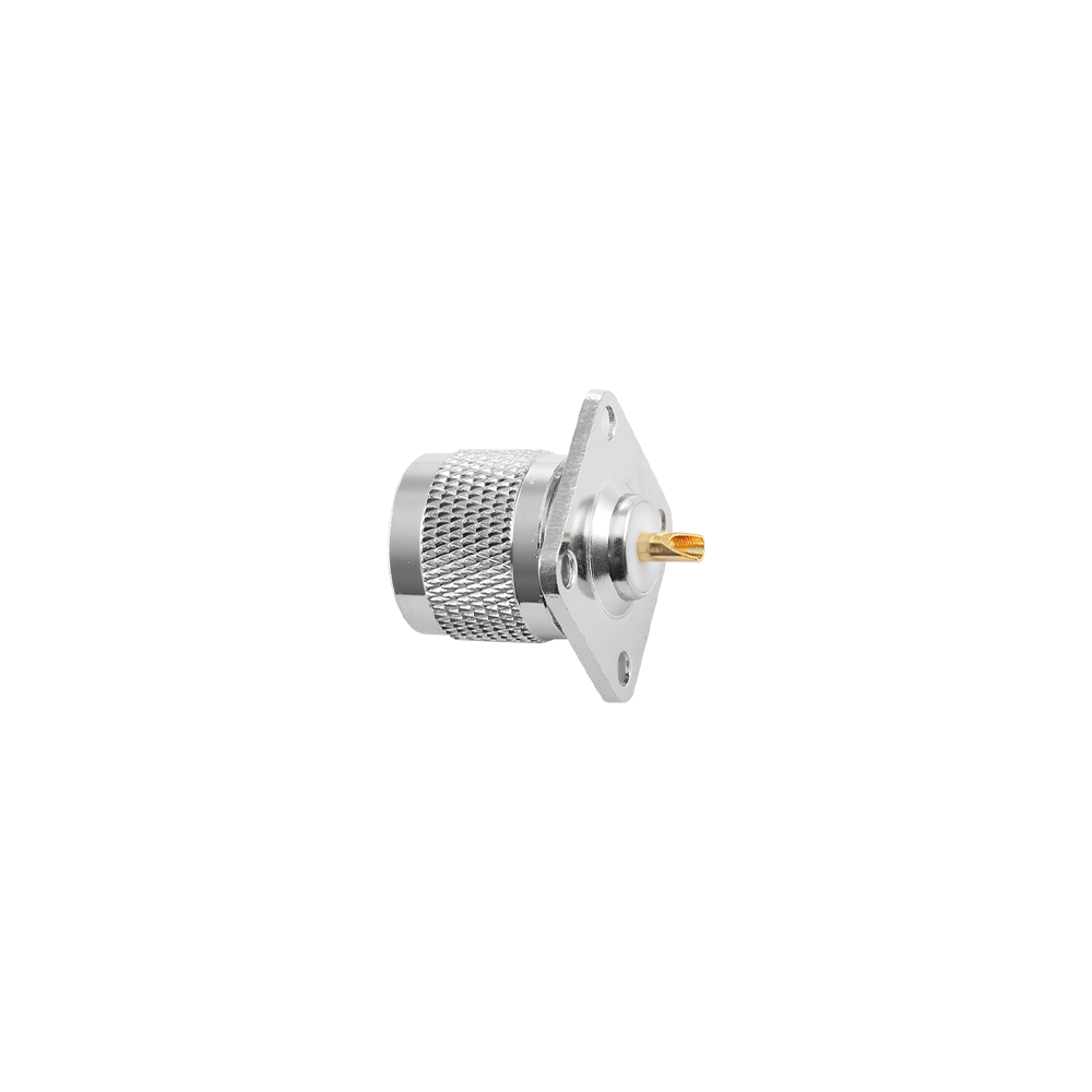
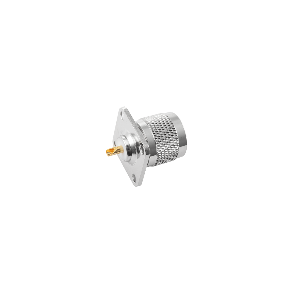
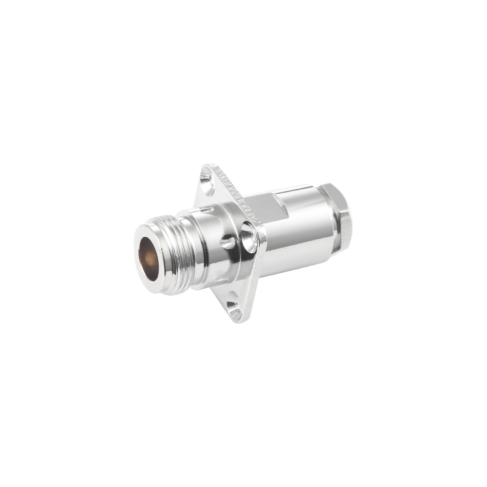
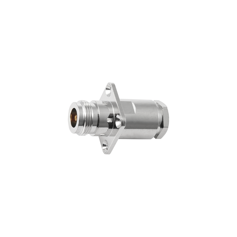
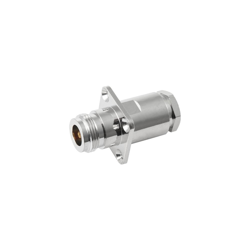
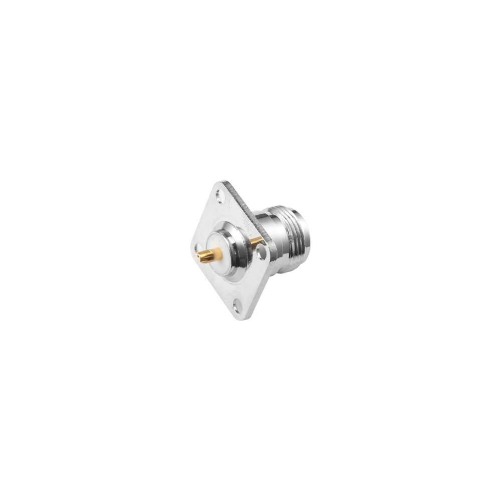
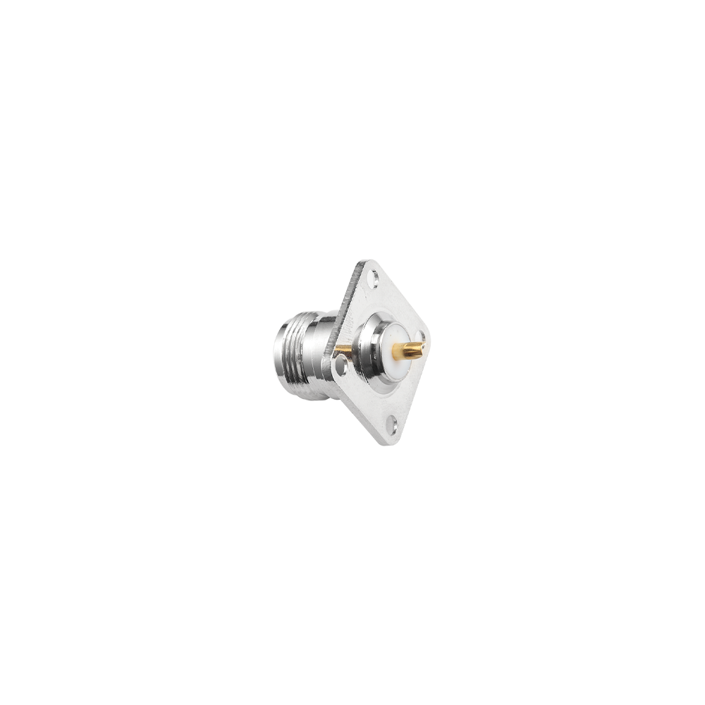
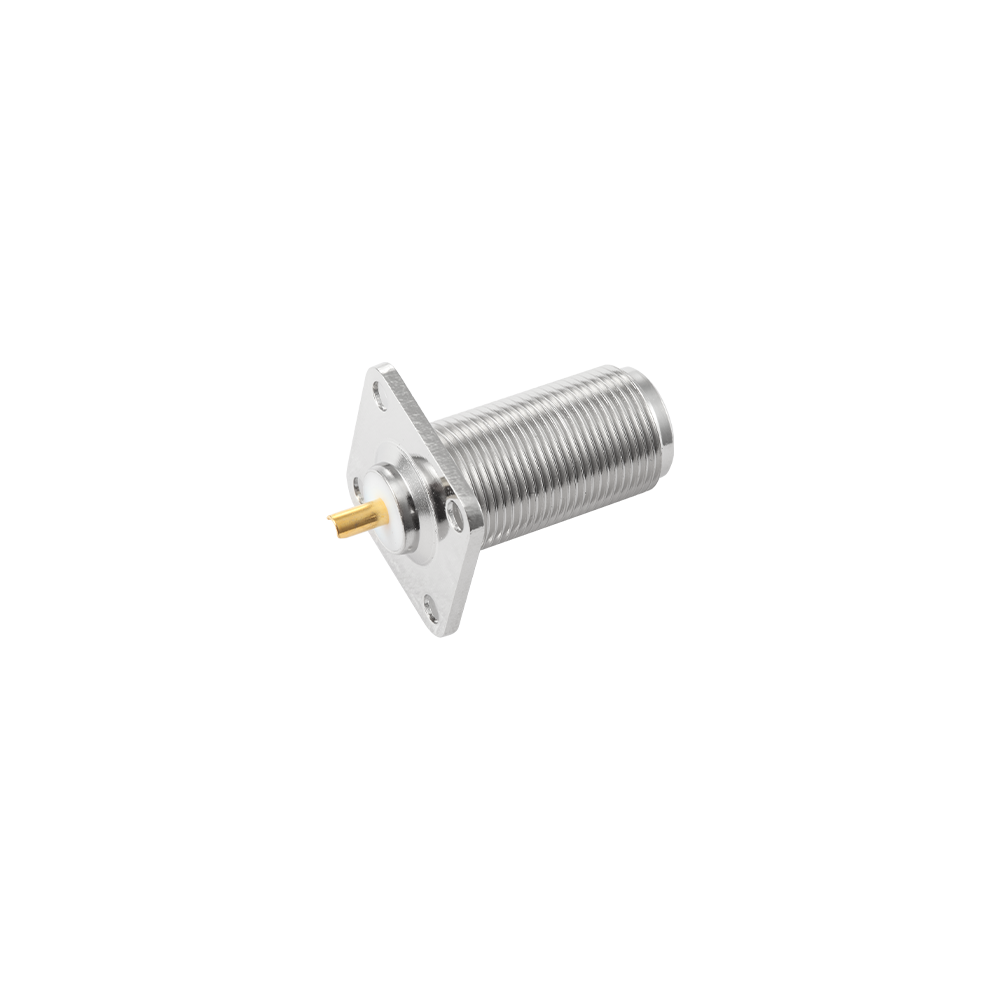
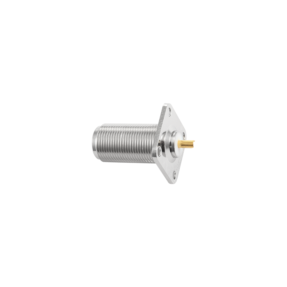
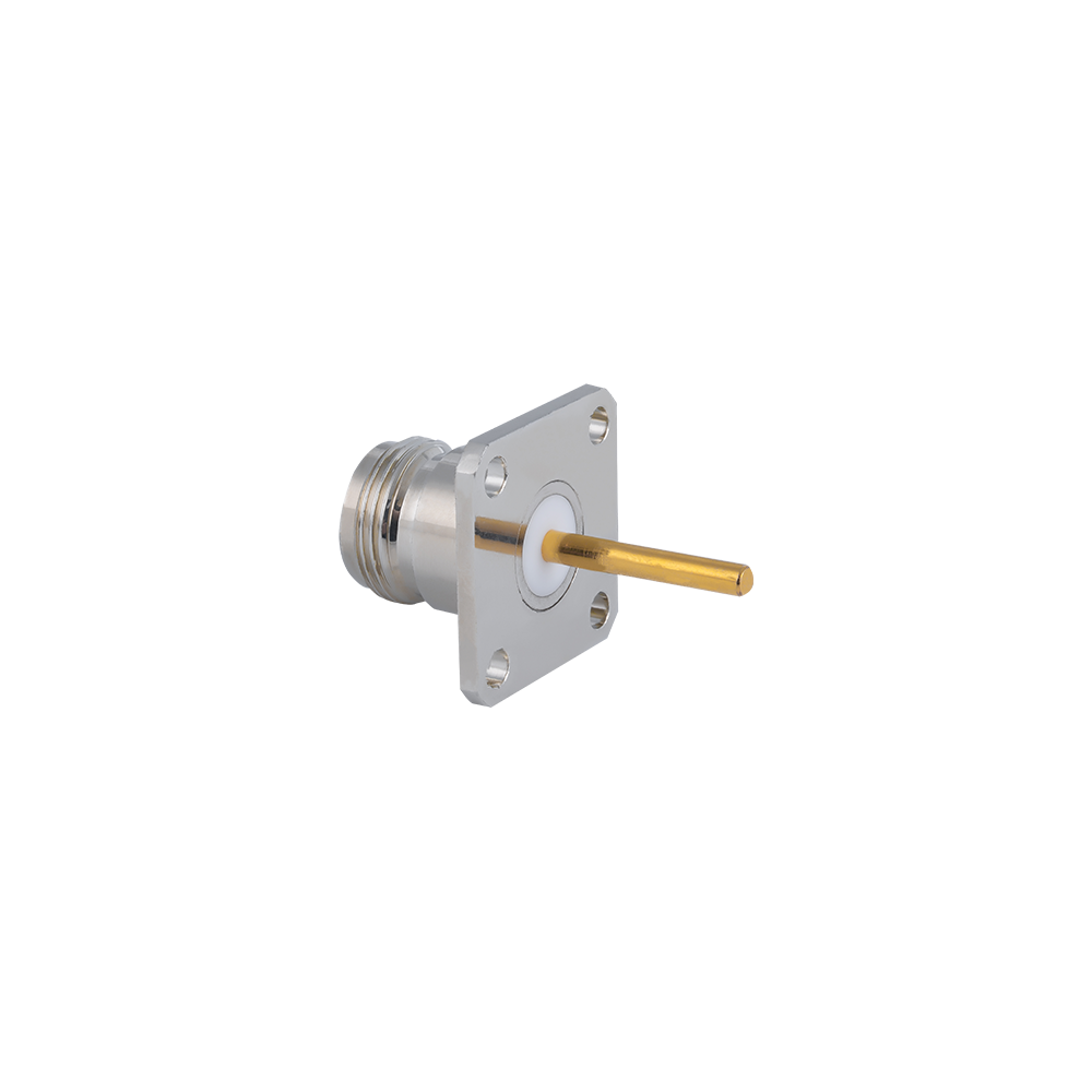
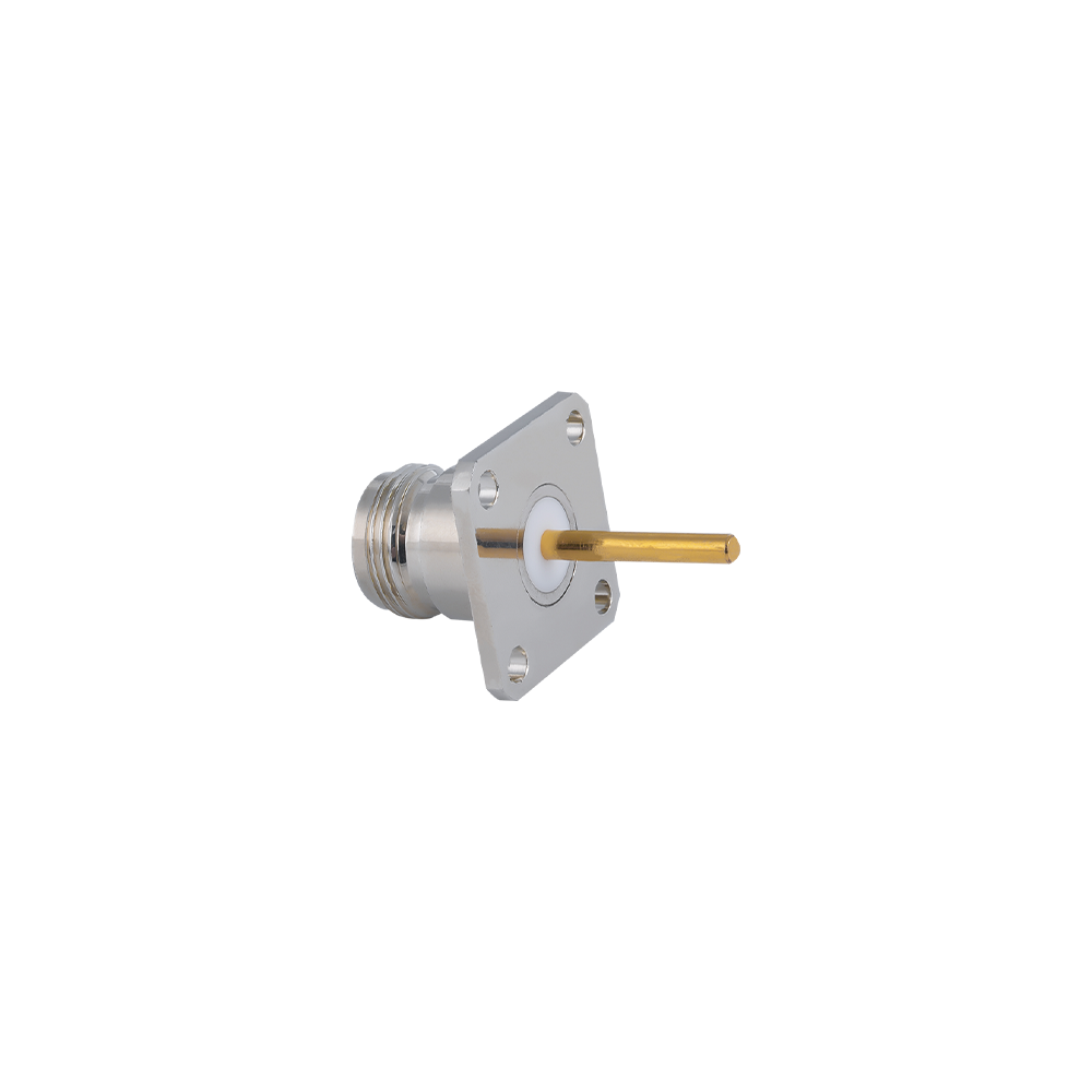
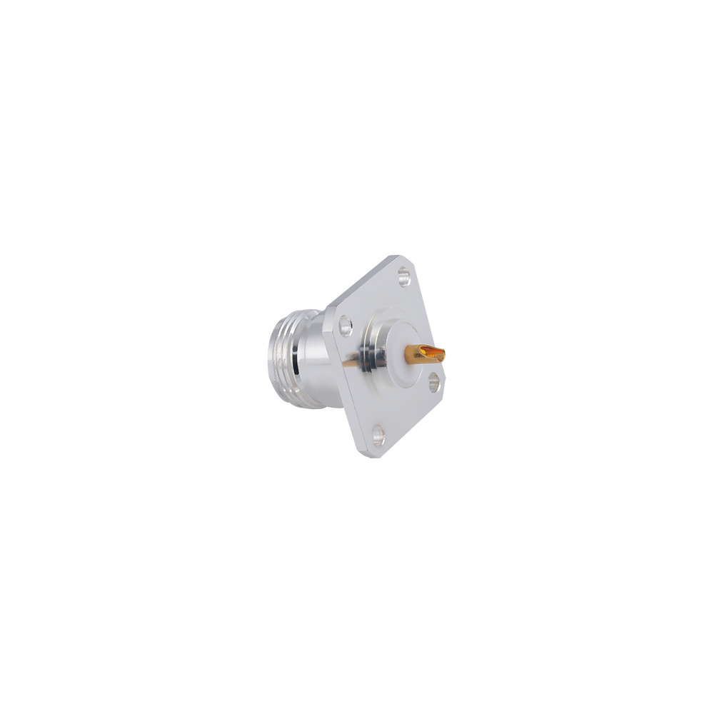
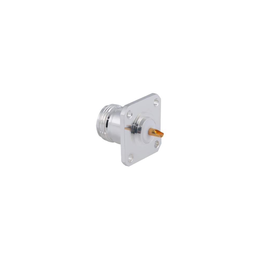
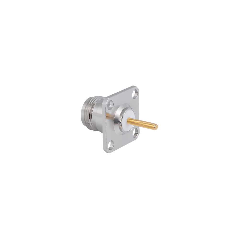
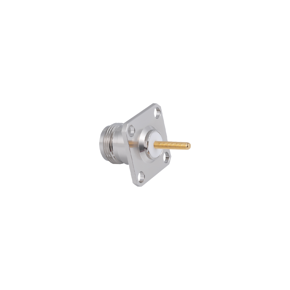
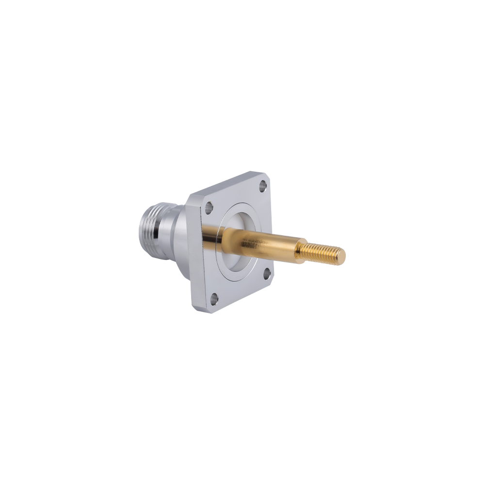
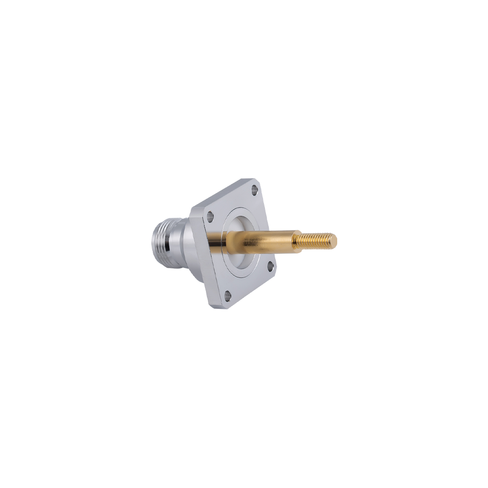
N-type Flange Mount Connectors are the panel-feedthrough solution of choice for ground stations, radar pedestals, outdoor communication shelters, and any equipment enclosure where RF panel ports must endure sustained mechanical loads, weather exposure, and vibration profiles that would exceed the capacity of single-hole bulkhead mounting systems. The N-type's larger body diameter, compared to TNC or SMA, provides inherently greater mechanical leverage at the panel interface—and the additional bolting points of the flange format extend this advantage further.
With 50Ω and 75Ω variants available, N-type flange mount connectors serve as the boundary between the external antenna or cable infrastructure and the equipment's internal RF circuitry across a remarkably diverse range of applications: from 75Ω CATV and broadcast distribution headend equipment to 50Ω radar and communications base stations. Jingcheng's flange mount series is manufactured with close attention to the flatness of the flange mounting face and the coaxiality of the through-body bore—both parameters that directly affect VSWR at the panel interface and the long-term mechanical integrity of the mount.
Key Features
Four-hole square flange and two-hole mounting configurations available; flange dimensions standardized for compatibility with industry-standard panel cutout patterns.
50Ω and 75Ω versions in the same flange-mount body platform—enabling system designers to specify a single connector family across mixed-impedance panel layouts.
Solder cup, solder-post, crimp, and PC-tail rear termination options; all termination methods maintain the specified 50Ω or 75Ω impedance through the PCB or cable interface.
Panel sealing with silicone or EPDM O-ring/gasket for IP65 or IP67 rated installations; stainless steel hardware kit available for outdoor mounting.
Operating temperature range -55°C to +155°C (standard); PE dielectric cable versions -40°C to +85°C.
Corrosion-resistant body options: tri-metal plated brass (72-hour salt spray as standard), passivated stainless steel (96+ hour salt spray), and anodized aluminum (weight-critical outdoor enclosures).
Competitive Advantages
Jingcheng's quality management system, certified to both ISO9001 and GJB9001A, requires that each production lot of flange mount connectors be accompanied by an inspection record covering dimensional checks of the flange face flatness, through-bore coaxiality, and thread gauge verification. This documentation is available to customers on request and is accepted by prime contractors for incoming quality verification.
The 75Ω N-type flange mount series is less commonly stocked by generic connector distributors than the 50Ω version. Jingcheng maintains both impedances in its standard catalogue, shortening lead time for system integrators building mixed-impedance equipment.
Custom flange drilling patterns, extended body lengths, and non-standard rear termination combinations are available as engineering specials with 3–4 week lead times, supported by Jingcheng's in-house tooling and CNC machining capability.
Typical Applications
CATV and broadcast signal distribution headend equipment rear panels (75Ω)
Ground station antenna feed switching panels for satellite communications
Outdoor base station radio unit (RRU) RF interface panels
Military field communication shelter and command-post RF patch panels
Power amplifier and LNA module RF input/output panel ports
FAQ
Q: Is there an N-type flange mount connector suitable for pressurized waveguide or coaxial line systems?
A: Yes. Versions with hermetic sealing (glass-to-metal seal on the center contact) are available as engineering specials for pressurized transmission line interfaces. Please specify the required gas type, operating pressure, and proof pressure in your inquiry.
Q: What rear termination is recommended for direct PCB mounting of N-type flange connectors?
A: For PCB direct mount, a solder-post (through-hole PC tail) rear termination is recommended. The large N-type body provides inherent rigidity, but an additional grounding tab or mounting foot should be specified for PCB assemblies that will be subjected to cable pull forces exceeding the solder joint capacity. Contact our engineering team for the specific PCB-mount version drawing.
Q: Can the flange be supplied in a non-magnetic (non-ferrous) material for MRI-adjacent installations?
A: Yes. Aluminum and austenitic stainless steel body variants are non-magnetic and suitable for MRI-adjacent or low-magnetic-field environments. Please specify the application and any magnetic permeability requirement when ordering.
|
Temperature Range |
-55~+155℃(PE Cable -40~+85℃) |
|
Impedance |
50Ω, 75Ω |
|
Frequency Range |
DC~11GHz |
|
Insulation resistance |
≥5000MΩ |
|
Insertion loss |
≤0.2dB(6GHz) |
|
VSWR |
Straight ≤1.15/6GHz |
|
Right angle |
≤1.25/6GHz |
|
Durability(mating) |
≥500 (cycles) |