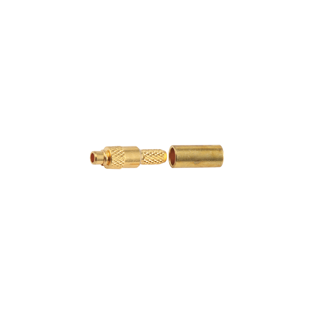
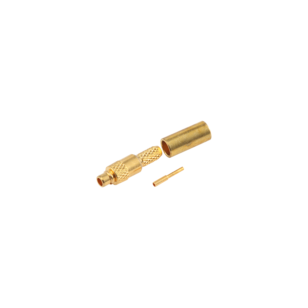
The RPMMCX reverse polarity series extends the RP convention to the MMCX ultra-miniature snap-on interface — the smallest snap-lock RF connector in common use — providing interface segregation in the most space-constrained wireless device applications such as embedded WLAN modules, wearable IoT devices, and miniaturized M2M communication modules
Yangzhou Jingcheng Electronics Co., Ltd., a premier China RPMMCX Reverse Polarity Connectors Manufacturer and RPMMCX Reverse Polarity Connectors Factory, was founded in 1999. It is a high-tech enterprise specializing in the R&D and manufacturing of RF coaxial connectors, cable assemblies, and passive microwave components.
Equipped with a comprehensive R&D and production system, the company has obtained international certifications including ISO9001. Adhering strictly to standards such as MIL, IEC and GB, we offer over 30 product series with more than 2,000 specifications, covering SMA, BNC, N-type and other mainstream models. Our products are widely applied in the fields of communications, aerospace, automotive electronics and beyond, and exported to many countries and regions across Europe, America and Asia.
We uphold the tenet of "Quality as the Foundation, Customers as the Core", committed to providing reliable interconnection solutions and professional services for global clients.
RPMMCX Reverse Polarity Connectors Industry knowledge
1. Ultra-Miniature Interconnect for Space-Constrained Wireless Design
The RPMMCX reverse polarity connector represents the intersection of two distinct engineering requirements in modern wireless product design: the need for an ultra-compact coaxial interconnect and the regulatory mandate for antenna attachment segregation. Derived from the MMCX (Micro-Miniature Coaxial) interface—which is itself approximately 30% smaller than the SMB connector—the RPMMCX variant applies the reverse polarity centre contact convention to create a physically tiny interface that also prevents accidental mating with standard MMCX equipment. This combination of extreme miniaturisation and polarity protection makes the RPMMCX reverse polarity connector a preferred solution for products where board space is at an absolute premium and where FCC Part 15 compliance is required.
The MMCX interface, standardised under IEC 61169-52, was originally developed to provide a high-frequency, miniature interconnect solution that could be terminated on small-diameter coaxial cables while maintaining a maximum operating frequency of 6 GHz. The interface features a snap-on coupling mechanism that enables rapid, tool-less mating and unmating—a feature that is particularly valued in portable and field-deployable equipment where antenna changes may be required. The RPMMCX reverse polarity connector retains all these mechanical and electrical characteristics while reversing the centre contact gender: the plug (male body) has a centre socket, and the jack (female body) has a centre pin. This configuration is visually indistinguishable from standard MMCX at a glance, requiring inspection of the centre contact for positive identification.
From a mechanical perspective, the RPMMCX connector is designed for repeated mating cycles—typically 500 minimum—with an engagement force not exceeding 20 N and a disengagement force of at least 10 N. The outer body is machined from brass and finished with gold plating over nickel, providing excellent corrosion resistance and low contact resistance. The centre contact is manufactured from beryllium copper, a material chosen for its combination of electrical conductivity and mechanical spring properties, which ensures consistent contact pressure across the connector's service life. Operating temperature ranges from -65°C to +165°C, accommodating the wide thermal environments encountered in automotive, aerospace, and outdoor wireless applications. The connector's compact dimensions—typically 3.5 mm outer diameter and 6.5 mm overall length—enable dense PCB layouts that would be impossible with larger connector formats.
Distinctive Characteristics of RPMMCX Reverse Polarity Connectors:
Ultra-compact footprint: approximately 50% of SMA size, 30% smaller than SMB
Snap-on coupling with positive engagement feedback for tool-less operation
Centre contact reversal: plug carries socket, jack carries pin
50Ω impedance with DC to 6 GHz frequency coverage
Gold-plated brass construction with beryllium copper centre contact
Prevents mismating with standard MMCX equipment
FCC Part 15.203 compliant for antenna attachment
2. The MMCX Family: Understanding the Size Advantage
To appreciate the value proposition of the RPMMCX reverse polarity connector, it is necessary to understand where it sits within the broader hierarchy of coaxial connector sizes. The SMA connector, widely used in test equipment and microwave applications, represents the reference point at 100% of typical footprint. The SMB connector, with its snap-on coupling and slightly smaller dimensions, occupies approximately 70% of the SMA footprint. The MMCX connector—and by extension the RPMMCX variant—occupies approximately 50% of the SMA footprint, representing a significant reduction in board area consumption.
This size reduction is not merely a cosmetic difference; it translates directly into practical engineering benefits. For PCB designers, the smaller footprint means that multiple connectors can be placed in a given area, enabling MIMO antenna configurations, multi-band operation, or redundant signal paths without requiring larger board sizes. For product designers, the reduced connector height allows for thinner product enclosures, which is particularly valuable in portable and wearable device categories. For system integrators, the lighter weight of the connector and its associated cable assembly contributes to overall product weight reduction—a meaningful factor in handheld and battery-powered equipment.
The following bar chart provides a comparative visualisation of the footprint reduction achieved by the RPMMCX connector relative to SMA and SMB interfaces. The chart uses the SMA connector footprint as the reference (100%) and expresses the other connector sizes as a percentage of that reference. This format makes it immediately apparent that the RPMMCX connector offers a substantial space-saving advantage—approximately 50% of the SMA footprint and 30% smaller than the SMB connector.
The bar chart above clearly demonstrates the footprint reduction progression from SMA to SMB to MMCX. The SMA connector, with its robust threaded coupling and higher frequency capability, occupies the largest footprint. The SMB connector reduces the footprint by approximately 30% through its use of a snap-on coupling mechanism and smaller outer conductor diameter. The MMCX connector—and consequently the RPMMCX variant—achieves a further reduction to approximately 50% of the SMA footprint, representing a 30% reduction relative to SMB. This size reduction is achieved through several design features: a smaller outer conductor diameter, reduced overall length, and a more compact snap-on mechanism. The smaller size does not come at the expense of electrical performance; the RPMMCX connector maintains 50Ω impedance and supports frequencies up to 6 GHz. This combination of ultra-compact footprint and maintained electrical performance makes the RPMMCX connector an attractive option for high-density PCB designs where both space and signal integrity are critical constraints. For engineers evaluating connector options for next-generation wireless products, the footprint comparison chart provides a quantitative basis for justifying the selection of the RPMMCX interface.
3. Polarity Convention and Visual Identification
The polarity convention of the RPMMCX reverse polarity connector is the source of most confusion encountered by engineers, procurement teams, and installers. In standard MMCX connectors, the gender of the connector is determined by the centre contact: a male connector has a centre pin, and a female connector has a centre socket. In the reverse polarity version, this relationship is inverted: an RPMMCX male plug has a centre socket, and an RPMMCX female jack has a centre pin. The external body, including the snap-on coupling mechanism and outer conductor, remains identical to standard MMCX.
This inversion was introduced as a means of complying with FCC Part 15.203, which requires that intentional radiators be designed to ensure that no antenna other than the one furnished by the responsible party can be used with the device. By reversing the centre contact, manufacturers created a connector that appears externally identical to a standard connector but cannot mate with it, thereby preventing consumers from attaching unauthorised antennas. The FCC has recognised MMCX and reverse polarity MMCX connectors as acceptable non-standard interfaces for meeting this requirement, provided that the connector is not readily available to consumers through general-purpose retail channels.
The table below summarises the polarity convention for both standard MMCX and RPMMCX connectors, providing a quick reference for engineers and procurement personnel.
Table 1: Polarity Convention - Standard MMCX vs. RPMMCX
Configuration
Body Gender
Centre Contact
Polarity Type
Standard MMCX Male
Male (snap-on barrel)
Pin
Standard
Standard MMCX Female
Female (snap-on socket)
Socket
Standard
RPMMCX Male (Plug)
Male (snap-on barrel)
Socket
Reverse
RPMMCX Female (Jack)
Female (snap-on socket)
Pin
Reverse
The table above provides a clear reference for the polarity convention of both standard and reverse polarity MMCX connectors. The key observation is that the body gender does not determine the centre contact gender in reverse polarity connectors. An RPMMCX male (plug) has a male body—which would normally indicate a pin centre contact—but it carries a centre socket. Similarly, an RPMMCX female (jack) has a female body but carries a centre pin. This inversion is the defining characteristic of the RPMMCX reverse polarity connector and is the mechanism that prevents mating with standard MMCX connectors. When ordering or specifying these connectors, it is essential to confirm both the body gender and the centre contact configuration. Many ordering errors occur because the buyer assumes that the body gender determines the centre contact, which is true for standard polarity connectors but false for reverse polarity connectors. Clear polarity marking on connector packaging and documentation helps mitigate this risk, but visual inspection of the centre contact remains the most reliable identification method.
4. Electrical Performance and Signal Integrity Considerations
The electrical performance of the RPMMCX reverse polarity connector is governed by the same design parameters as the standard MMCX connector, with the reverse polarity centre contact being the only electrical difference. The characteristic impedance is 50Ω, which is the standard for RF and microwave systems. The maximum operating frequency is 6 GHz, which covers the majority of contemporary wireless communication bands, including Wi-Fi 2.4 GHz, 5 GHz, and 6 GHz (Wi-Fi 6E), GPS L1/L2/L5, and Sub-GHz IoT bands.
The insertion loss of the RPMMCX connector is specified as 0.10 dB maximum at 1 GHz, with the loss increasing gradually with frequency to approximately 0.15 dB at 6 GHz. This low insertion loss ensures that signal power is transferred from the transmission line to the antenna or device input with minimal attenuation. The VSWR is 1.3 maximum (-18 dB return loss) across the full DC to 6 GHz frequency range, indicating that the connector presents a well-matched impedance to the transmission line and does not cause significant signal reflections. The RF leakage is -60 dB maximum at 1 GHz, providing good shielding effectiveness that prevents signal leakage and reduces interference with adjacent circuitry.
The power handling capability of the RPMMCX connector is 95 W maximum at 1 GHz at 25°C, derating with increasing frequency and temperature. This power rating is more than sufficient for the low-power wireless applications where the RPMMCX connector is typically deployed, such as IoT sensors, GPS receivers, and portable wireless modules. The voltage rating is 2255 V RMS maximum continuous, with a dielectric withstanding voltage of 1000 V RMS. The insulation resistance is 10000 MΩ minimum, ensuring that leakage currents are negligible. The centre contact resistance is 5 mΩ minimum, which represents a low-resistance connection that contributes to the low insertion loss.
The following line chart presents the typical insertion loss of the RPMMCX connector across the DC to 6 GHz frequency range, demonstrating the flat frequency response that ensures consistent signal quality across all operating bands.
The line chart above presents the typical insertion loss profile of the RPMMCX reverse polarity connector across the DC to 6 GHz frequency range. The insertion loss remains consistently below 0.05 dB from DC through approximately 4 GHz, rising gradually to 0.08 dB at 6 GHz. The 0.10 dB reference line (dashed) indicates the maximum specified insertion loss at 1 GHz. This flat, low-loss response ensures that the connector introduces minimal attenuation to the RF signal path, preserving both transmitted power and received signal strength. The low insertion loss is particularly important in battery-powered wireless devices, where every milliwatt of transmitter power is precious and every decibel of receiver sensitivity matters. The slight rise in insertion loss at higher frequencies is expected due to skin effect losses in the centre conductor and dielectric losses in the insulator material. The VSWR remains below 1.3:1 across the entire band, indicating that the connector presents a well-matched impedance to the transmission line. This impedance stability is achieved through careful design of the connector's internal geometry, including the dimensions of the centre conductor, insulator, and outer conductor. The use of precision-machined brass components and gold-plated contact surfaces ensures consistent electrical performance across the connector's service life. For designers of wireless modules and portable RF equipment, this insertion loss profile provides confidence that the connector will not be a significant source of signal degradation in the RF path.
5. Application Distribution and Industry Adoption
The RPMMCX reverse polarity connector has found adoption across several industry sectors where ultra-compact form factor and regulatory compliance are both critical requirements. The following chart provides an estimated distribution of RPMMCX connector deployments across major application categories.
The bar chart above shows the estimated application distribution of RPMMCX reverse polarity connectors across four major application categories. Portable and handheld wireless devices—including tablets, portable test equipment, and consumer electronics with external antenna options—represent the largest segment at 32%. These devices benefit from the ultra-compact footprint of the RPMMCX connector, which allows for antenna connection without consuming significant board area. IoT and embedded wireless modules account for 28% of deployments, driven by the growing adoption of wireless connectivity in industrial, automotive, and smart home applications. GPS and GNSS receivers represent 24%, where the RPMMCX connector provides the small-form-factor antenna connection required for portable and automotive navigation systems. Wearable RF electronics comprise the remaining 16%, where the lightweight and compact nature of the RPMMCX connector aligns with the size and weight constraints of wrist-worn and body-worn devices. This distribution reflects the RPMMCX connector's position as a solution for applications where both size reduction and regulatory compliance are critical design drivers. The connector's reverse polarity interface ensures that devices remain compliant with FCC Part 15.203, while its ultra-compact footprint enables the miniaturisation required by contemporary portable and wearable product categories.
6. Configuration Options and Application-Specific Variants
The RPMMCX reverse polarity connector is available in a variety of configurations to accommodate different mounting, termination, and cable requirements. The most common configurations include cable-mount plugs and jacks for cable assembly applications, surface-mount (SMD) and through-hole PCB connectors for direct board mounting, and bulkhead or edge-mount versions for panel pass-through applications. Each configuration is designed to meet the specific mechanical constraints of the target application while maintaining consistent electrical performance.
Cable-mount RPMMCX connectors are available in both crimp and solder termination styles, accommodating a range of miniature coaxial cable types including RG-178, RG-196, RG-174, RG-316, LMR-100, and Belden 7805. The crimp style provides a quick, consistent termination suitable for volume production, while the solder style offers a more compact termination profile suitable for applications where cable strain relief is not required. The choice of termination style should be based on the cable type, production volume, and required cable retention force. Cable-mount connectors are typically supplied with a cable strain relief boot or heat-shrink tubing to provide mechanical support at the cable-to-connector junction.
PCB-mount RPMMCX connectors are available in both surface-mount and through-hole styles, with vertical and right-angle orientations to accommodate different board layouts and enclosure designs. The surface-mount version is suitable for high-density, automated assembly processes, while the through-hole version provides greater mechanical strength and is preferred for applications where the connector is subject to repeated mating cycles. Both mounting styles are designed to maintain the 50Ω characteristic impedance through the board transition, ensuring consistent electrical performance from the cable to the PCB trace. The following illustration provides an overview of the key configuration options available.
The illustration above summarises the three primary configuration categories for RPMMCX reverse polarity connectors: cable-mount (crimp or solder termination), SMD PCB mount (automated assembly), and through-hole PCB mount (high mechanical retention). Each configuration category includes variants with different orientations (vertical, right-angle, edge-mount) to accommodate diverse board layouts and enclosure designs. The cable-mount configuration is typically used for antenna cable assemblies and test leads, where the connector is terminated to a coaxial cable. The SMD PCB mount configuration is suitable for high-volume automated assembly processes, where pick-and-place equipment can accurately position the connector on the PCB before reflow soldering. The through-hole configuration provides greater mechanical strength and is preferred for applications where the connector is subject to repeated mating cycles or where the PCB is subject to vibration. The choice of configuration should be based on the specific requirements of the application, including board space availability, cable routing constraints, production volume, and expected mating cycle count. Yangzhou Jingcheng Electronics offers all three configuration categories, with detailed specifications and mechanical drawings available for each variant to support engineering design and procurement decisions.
7. Mating and Unmating Considerations
The snap-on coupling mechanism of the RPMMCX reverse polarity connector provides a convenient, tool-free mating experience, but it also requires careful handling to ensure reliable electrical contact and long service life. The connector is designed for 500 mating cycles minimum, with an engagement force not exceeding 20 N and a disengagement force of at least 10 N. The engagement force is the axial force required to push the plug fully into the jack until the snap-on mechanism engages with an audible and tactile click. The disengagement force is the axial force required to separate the connectors when pulled straight apart.
To achieve the rated service life and maintain electrical performance, the following practices should be observed when mating and unmating RPMMCX connectors. First, ensure that the connectors are properly aligned before applying axial force; misalignment can cause the centre contact to be damaged or the snap-on mechanism to be deformed. Second, apply force smoothly and directly along the axis of the connector; off-axis force can cause bending or deformation of the outer conductor. Third, avoid twisting the connector during mating or unmating; the snap-on mechanism is not designed to accommodate rotational force. Fourth, when unmating, pull the connector straight back without applying rotational force or prying; the disengagement force should be sufficient to separate the connectors without the need for tools.
Visual inspection before each mating is recommended to ensure that the centre contact is clean and free from damage, and that the snap-on mechanism is free from deformation or foreign debris. Contamination on the centre contact can increase contact resistance and degrade RF performance, while deformation of the snap-on mechanism can reduce retention force and increase the risk of accidental disconnection. If a connector shows signs of damage, it should be replaced immediately to prevent damage to the mating connector and to ensure reliable electrical performance.
8. Regulatory Compliance and Standards Conformance
The RPMMCX reverse polarity connector is designed and manufactured to conform to the applicable international standards and regulatory requirements. The MMCX interface is standardised under IEC 61169-52, which specifies the dimensional and performance requirements for MMCX connectors used in 50Ω cable networks with an operating frequency limit up to 6 GHz. This standard ensures that connectors from different manufacturers are mechanically and electrically interoperable, providing confidence in the supply chain.
The reverse polarity variant (RPMMCX) is not explicitly addressed in the IEC standard, as the polarity convention is a market-driven differentiator rather than a standardised parameter. However, the reverse polarity version maintains the same dimensional and electrical characteristics as the standard MMCX connector, with the centre contact gender being the only difference. This means that RPMMCX connectors are physically and electrically compatible with standard MMCX equipment in all respects except for centre contact mating, which prevents accidental interconnection.
For FCC compliance, the reverse polarity interface provides the antenna attachment segregation required by 47 CFR Part 15.203. The FCC has recognised the reverse polarity MMCX connector as an acceptable non-standard interface for meeting the requirement that intentional radiators be designed to ensure that no antenna other than the one furnished by the responsible party can be used with the device. The use of a reverse polarity connector is considered a legitimate approach to meeting this requirement, provided that the connector is not commonly available through general-purpose retail channels.
9. Manufacturing and Supply Chain Quality
Yangzhou Jingcheng Electronics Co., Ltd., established in 1999, manufactures RPMMCX reverse polarity connectors under ISO9001 certification, adhering to MIL, IEC, and GB standards. The company's production process includes precision machining of brass bodies, gold plating over nickel for corrosion resistance and low contact resistance, and precise assembly of the centre contact to achieve the correct polarity configuration. The use of beryllium copper for the centre contact provides the required combination of electrical conductivity and mechanical spring properties.
Each RPMMCX connector undergoes 100% inspection for dimensional accuracy, contact integrity, and electrical performance before shipment. Dimensional inspection ensures that the connector meets the interface requirements of IEC 61169-52, while electrical testing verifies that the connector meets the specified impedance, insertion loss, and VSWR requirements. The company's over 30 product series and more than 2,000 specifications covering SMA, BNC, N-type, MCX, MMCX, and other configurations provide a broad foundation for consistent manufacturing quality. Environmental testing per MIL-STD-202 for thermal shock, corrosion, vibration, mechanical shock, and moisture resistance ensures that the connectors meet the durability requirements of demanding applications.
10. Frequently Asked Questions
(1) What does RPMMCX stand for?
RPMMCX stands for Reverse Polarity Micro-Miniature Coaxial. The "RP" prefix indicates that the centre contact gender is reversed relative to the connector body: an RPMMCX male plug has a centre socket, and an RPMMCX female jack has a centre pin.
(2) What is the difference between MMCX and RPMMCX?
The difference lies in the centre contact gender. In standard MMCX, a male connector has a centre pin and a female connector has a centre socket. In RPMMCX, a male plug has a centre socket and a female jack has a centre pin. All other mechanical and electrical characteristics remain identical.
(3) Why would a device use RPMMCX instead of standard MMCX?
Devices use RPMMCX to comply with FCC Part 15.203, which requires that intentional radiators be designed to ensure that no antenna other than the one furnished by the manufacturer can be used with the device. The reverse polarity interface prevents consumers from attaching unauthorised antennas.
(4) What is the frequency range of RPMMCX connectors?
RPMMCX connectors provide repeatable electrical performance from DC to 6 GHz. The actual frequency range depends on the cable type and connector construction, with higher-performance cables supporting operation up to the full 6 GHz specification.
(5) Can a standard MMCX connector mate with an RPMMCX connector?
No, a standard MMCX connector cannot mate with an RPMMCX connector of the same body gender because the centre contact genders do not match. Attempting to force mating can damage the centre contacts. Adapters are available to convert between standard MMCX and RPMMCX interfaces when necessary.
(6) What cable types are compatible with RPMMCX connectors?
RPMMCX connectors are available with terminations compatible with RG-178, RG-196, RG-174, RG-316, LMR-100, and Belden 7805 cables. The termination method (crimp or solder) should be selected based on the cable type and installation requirements.
(7) What is the IEC standard for MMCX connectors?
The MMCX connector is standardised under IEC 61169-52, which provides the sectional specification for series MMCX RF coaxial connectors with snap-on coupling, typically for use in 50Ω cable networks with an operating frequency limit of up to 6 GHz.
11. Standards Compliance and Documentation
RPMMCX reverse polarity connectors manufactured under ISO9001 certification comply with the relevant interface standards—including IEC 61169-52 for MMCX connectors—and FCC Part 15.203 for antenna attachment compliance. All products are RoHS compliant and manufactured using environmentally controlled processes. Environmental testing is performed per MIL-STD-202 for thermal shock, corrosion, vibration, mechanical shock, and moisture resistance. The company provides detailed datasheets for each connector series, including dimensional drawings, electrical specifications, and environmental ratings, to support engineering design and procurement decisions.
The compliance chart above highlights the key standards and regulatory requirements applicable to RPMMCX reverse polarity connectors. IEC 61169-52 provides the interface specification for MMCX connectors, ensuring dimensional and mechanical consistency across manufacturers. FCC Part 15 compliance verifies that the reverse polarity interface meets the antenna attachment requirements for intentional radiators. MIL-STD-202 certification confirms that the connectors have been tested for thermal shock, corrosion, vibration, mechanical shock, and moisture resistance. RoHS compliance ensures that the connectors are manufactured using environmentally controlled processes. This multi-standard approach ensures that RPMMCX connectors meet the quality and reliability expectations of global wireless, communications, and aerospace industries.


 English
 中文简体
中文简体