English
 中文简体
中文简体FME PCB Connectors Manufacturer
Product Overview
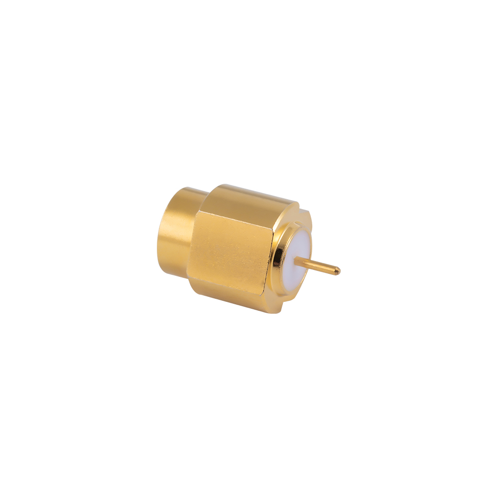
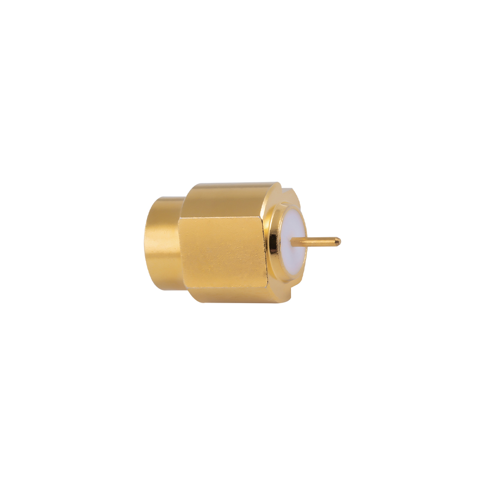
The FME PCB connector mounts directly onto a printed circuit board, providing a panel-accessible FME mating interface that allows antenna cables to be connected directly to the board-level RF circuitry of compact wireless modules, automotive telematics PCBs, and IoT device mainboards — eliminating the pigtail cable assembly that would otherwise be required between an off-board connector and the PCB trace.
Key Features
Through-hole and SMT mounting options for compatibility with both wave-solder and reflow PCB assembly processes
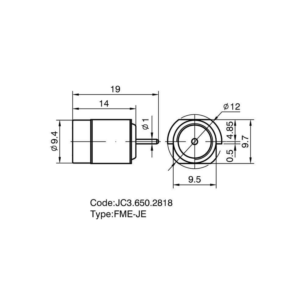
Precision center pin height and board alignment geometry ensuring consistent 50 Ω impedance at the PCB-to-connector transition
FME mating interface fully conforming to FME connector standard for universal mating compatibility with FME cable connectors
Compact board footprint allowing high-density PCB layouts in miniaturized wireless module designs
Robust mechanical retention via PCB mount flange or through-hole solder posts, providing resistance to cable mating pull-out forces
Gold-plated center contact and controlled plating on outer body for reliable solderability and long-term contact resistance stability
Low-profile body minimizing PCB board-height envelope for slim-profile device designs
RoHS-compliant; automotive PPAP documentation support available on request
Typical Applications
Automotive telematics control unit (TCU) and V2X module PCB antenna ports
Compact IoT mainboard direct antenna connection ports for smart home and industrial wireless devices
Mobile device and wearable technology RF module PCB antenna interfaces
Vehicle GPS/GNSS receiver module PCB antenna connection points
Compact wireless industrial sensor and gateway PCB RF ports
FAQ
Q: Can your FME PCB connectors be used in automotive-grade temperature environments?
A: Our FME PCB connectors are manufactured using materials and plating processes selected for the temperature and humidity cycling requirements of automotive electronics environments; customers with specific automotive qualification requirements should contact our team to discuss applicable testing and documentation.
Q: Do you provide a recommended PCB footprint and soldering guidelines for your FME PCB connectors?
A: Yes — recommended footprint, land pattern, and soldering process guidelines are supplied with each FME PCB connector model, and our engineering team can review customer Gerber files to confirm layout compatibility before PCB fabrication.