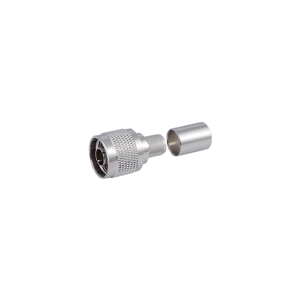
The RPN reverse polarity series applies the RP center conductor gender reversal to the N-type threaded interface — combining N-type's proven weatherproof, high-power capable mechanical design with RP interface segregation for outdoor WLAN infrastructure, high-power access points, and wireless bridge equipment where the robust N-type connector format is required alongside the interface separation of the RP convention.
Yangzhou Jingcheng Electronics Co., Ltd., a premier China RPN Reverse Polarity Connectors Manufacturer and RPN Reverse Polarity Connectors Factory, was founded in 1999. It is a high-tech enterprise specializing in the R&D and manufacturing of RF coaxial connectors, cable assemblies, and passive microwave components.
Equipped with a comprehensive R&D and production system, the company has obtained international certifications including ISO9001. Adhering strictly to standards such as MIL, IEC and GB, we offer over 30 product series with more than 2,000 specifications, covering SMA, BNC, N-type and other mainstream models. Our products are widely applied in the fields of communications, aerospace, automotive electronics and beyond, and exported to many countries and regions across Europe, America and Asia.
We uphold the tenet of "Quality as the Foundation, Customers as the Core", committed to providing reliable interconnection solutions and professional services for global clients.
RPN Reverse Polarity Connectors Industry knowledge
1. Introduction to RPN Reverse Polarity Connectors
The RPN reverse polarity connector applies the reversed centre contact convention to the N‑type threaded interface, combining the N‑type's weatherproof, high‑power mechanical design with the interface segregation required for regulatory compliance. This configuration is used in outdoor WLAN infrastructure, high‑power wireless access points, and point‑to‑point bridge equipment where the robust N‑type connector format is required alongside the separation provided by the reverse polarity convention.
The N‑type interface, from which the RPN connector is derived, is characterised by its threaded coupling (7/16‑28 UNF), weather‑resistant construction, and high power‑handling capability—typically up to several hundred watts in the HF through UHF bands. The RPN reverse polarity connector retains these attributes while reversing the centre contact gender: a reverse polarity N plug has a centre socket, and a reverse polarity N jack has a centre pin. This reversal is the defining characteristic of the RPN reverse polarity connector and is the mechanism by which it prevents accidental mating with standard N‑type connectors.
RPN connectors are designed for applications requiring reliable, non‑standard interface connections in outdoor and industrial environments where the robust N‑type mechanical construction is essential. They provide consistent electrical performance from DC to 11 GHz, with 50Ω characteristic impedance, making them suitable for a wide range of RF and wireless applications including outdoor Wi‑Fi (2.4 GHz, 5 GHz, 6 GHz), L‑band satellite communications, and land‑mobile radio (LMR) base stations. The threaded coupling ensures a secure, vibration‑resistant connection that withstands harsh environmental conditions.
Core Characteristics of RPN Reverse Polarity Connectors:
Centre contact gender reversed relative to the connector body (plug: socket; jack: pin)
50Ω characteristic impedance with DC to 11 GHz frequency coverage
Threaded coupling (7/16‑28 UNF) for vibration‑resistant, weatherproof connections
High power handling up to 300 W at 1 GHz for outdoor infrastructure
Prevents accidental mating with standard N‑type connectors
Compliant with FCC Part 15 antenna attachment requirements
Nickel‑plated brass construction for corrosion resistance
2. Interface Definition and Polarity Convention
Understanding the polarity convention of RPN reverse polarity connectors is essential for proper selection and mating. In standard polarity N‑type connectors, the gender is determined by the centre contact: a male connector has a centre pin, and a female connector has a centre socket. In reverse polarity N‑type connectors, this relationship is inverted: a reverse polarity N plug has a centre socket, and a reverse polarity N jack has a centre pin.
The connector body—including the threaded coupling mechanism (7/16‑28 UNF) and external housing—remains identical to the standard N‑type version. This means that the external appearance of an RPN connector is indistinguishable from a standard N‑type connector of the same body gender, and visual identification requires inspection of the centre contact rather than the connector shell. The threaded coupling provides a secure, weatherproof connection suitable for outdoor installations, with a coupling torque of 0.8 to 1.1 N·m typically recommended.
The deliberate mismatch of centre contact gender relative to the connector body serves two primary purposes: regulatory compliance and functional prevention of mismating with standard polarity equipment. The reversed centre contact ensures that users cannot inadvertently connect a standard N‑type antenna to an RPN device, which could potentially damage the device or degrade performance. This interface segregation is particularly important in outdoor WLAN infrastructure where antenna replacement by end users could compromise regulatory compliance.
The following illustration provides a visual reference for the polarity convention of RPN connectors. The diagram shows that while the external body remains identical between standard N‑type and RPN versions of the same gender, the centre contact is reversed. This reversal is the defining characteristic of RPN reverse polarity connectors and is the mechanism by which they prevent mismating with standard N‑type equipment.
The diagram above illustrates the polarity convention for standard N‑type and RPN connectors. In standard polarity N‑type connectors, the male has a centre pin and the female has a centre socket. In RPN connectors, the male (plug) has a centre socket and the female (jack) has a centre pin. The external threaded body remains identical between standard N‑type and RPN versions of the same gender. This reversal of the centre contact is what defines the RPN interface and is the mechanism by which these connectors prevent mismating with standard N‑type equipment. The diagram also highlights that the terms "male" and "female" in RPN connectors refer to the connector body, not the centre contact, which is the source of much of the confusion surrounding these connectors. When selecting an RPN connector, it is essential to verify both the body gender and the centre contact configuration to ensure proper mating with the corresponding equipment. Clear polarity marking on RPN connector products facilitates accurate identification and selection, reducing the risk of incorrect ordering and installation.
3. RPN vs. Standard N-Type: Key Differences
The RPN reverse polarity connector shares the vast majority of its mechanical and electrical characteristics with the standard N‑type connector, with the centre contact gender being the sole distinguishing feature. The following table summarises the key differences and commonalities between RPN and standard N‑type connectors.
Table 1: RPN vs. Standard N-Type Connector Comparison
Characteristic
Standard N-Type
RPN (Reverse Polarity)
Male (Plug) Centre Contact
Pin
Socket
Female (Jack) Centre Contact
Socket
Pin
Impedance
50 Ω
50 Ω
Frequency Range
DC - 11 GHz
DC - 11 GHz
Coupling Mechanism
Threaded (7/16-28 UNF)
Threaded (7/16-28 UNF)
Mating Cycles
500 minimum
500 minimum
FCC Part 15 Compliance
No
Yes
Prevents Mismating
No
Yes
The table above demonstrates that the RPN reverse polarity connector is electrically and mechanically identical to the standard N‑type connector in all respects except for the centre contact gender and the resulting regulatory compliance. The impedance, frequency range, threaded coupling mechanism, and mating cycle ratings are all shared between the two interfaces. This means that RPN connectors can be used in any application where standard N‑type connectors are used, provided that the mating connector is also of the reverse polarity type. The key advantage of the RPN connector is its ability to prevent accidental mating with standard N‑type equipment, which supports FCC Part 15 compliance for intentional radiators. This is particularly important for outdoor WLAN infrastructure where antenna replacement by end users could compromise regulatory compliance and system performance.
4. Electrical Performance and Frequency Characteristics
The electrical performance of RPN reverse polarity connectors is defined by several key parameters that directly impact signal integrity in RF and wireless applications. The connector provides consistent electrical performance from DC to 11 GHz, with 50Ω characteristic impedance being the standard for RF and wireless communication applications.
The maximum frequency of 11 GHz covers the majority of outdoor wireless communication bands, including Wi‑Fi 2.4 GHz, 5 GHz, and 6 GHz, as well as L‑band satellite communications (1–2 GHz), S‑band (2–4 GHz), and C‑band (4–8 GHz). The frequency range is cable‑dependent; higher‑performance cables can support operation up to the full 11 GHz specification. The voltage rating is 2500 VRMS maximum continuous, with a dielectric withstanding voltage of 1500 VRMS maximum, ensuring that the connector can withstand the voltage levels encountered in typical outdoor RF installations.
The insertion loss is 0.05 dB maximum at 1 GHz, which ensures that signal attenuation remains negligible, preserving receiver sensitivity and transmitter power. The VSWR is 1.15 maximum (-23 dB) from DC to 11 GHz, indicating excellent impedance matching and minimal signal reflections. The insulation resistance is 5000 MΩ minimum, and the centre contact resistance is 1.5 mΩ minimum. These low resistance values ensure that signal integrity is maintained and that power losses are minimised. The RF leakage is -60 dB maximum at 1 GHz, indicating excellent shielding effectiveness.
The following line chart presents typical insertion loss across the DC to 11 GHz frequency range for RPN connectors, demonstrating the flat response that ensures consistent signal quality across all operating frequencies.
The line chart above shows the typical insertion loss of RPN reverse polarity connectors across the DC to 11 GHz frequency range. The insertion loss remains below 0.05 dB through most of the frequency spectrum, rising gradually to approximately 0.10 dB at 11 GHz. The 0.05 dB reference level (dashed line) indicates the maximum specified insertion loss at 1 GHz. This flat frequency response ensures that signal attenuation remains consistent across all operating frequencies, which is particularly important for broadband outdoor wireless applications. The low insertion loss values ensure that receiver sensitivity is preserved and that transmitted power reaches the antenna with minimal attenuation. The VSWR remains below 1.15:1 across the entire band, indicating excellent impedance matching. This impedance stability is achieved through precision machining of the brass body and nickel‑plated contacts, which ensure consistent electrical performance across the connector's service life of 500 mating cycles minimum. The combination of low insertion loss, excellent VSWR, and high power handling makes the RPN connector suitable for a wide range of outdoor wireless applications where signal integrity is paramount.
5. Power Handling Capability
The RPN reverse polarity connector inherits the N‑type's robust power handling capability, making it suitable for outdoor WLAN infrastructure and high‑power wireless applications. The power handling is 300 W maximum at 1 GHz at 25°C, derating with increasing frequency and temperature. This high power rating enables the use of RPN connectors in point‑to‑point bridge equipment and outdoor access points with high transmit power.
The following bar chart illustrates the relative power handling capability of RPN connectors compared to other common connector types, demonstrating the N‑type's advantage for high‑power outdoor applications.
The bar chart above compares the illustrative power handling of RPN/N‑type connectors with SMA and TNC connectors at 1 GHz. SMA connectors handle approximately 100 W at 1 GHz, while TNC connectors handle approximately 150 W. N‑type and RPN connectors handle approximately 300 W, making them the preferred choice for high‑power outdoor WLAN infrastructure. This higher power rating is achieved through the larger conductor size and better heat dissipation characteristics of the N‑type interface. The power handling capability derates with increasing frequency and temperature; for example, at 2.4 GHz, the power rating may be reduced to 250 W, and at 5 GHz to 180 W. The environmental durability of the N‑type interface—including its weatherproof construction and corrosion‑resistant plating—further supports its use in outdoor applications. The threaded coupling ensures that the connection remains secure under vibration and thermal cycling, which is particularly important for tower‑mounted installations.
6. Application Scenarios and Industry Use
RPN reverse polarity connectors are deployed across a wide spectrum of outdoor wireless and high‑power applications where both regulatory compliance and robust mechanical construction are required. The primary applications include outdoor WLAN infrastructure, point‑to‑point bridge equipment, LMR base stations, and satellite communication ground terminals.
(1) Outdoor WLAN Infrastructure
In outdoor Wi‑Fi access points and mesh network nodes, RPN reverse polarity connectors provide the robust, weatherproof interface required for external antenna connections. The reverse polarity interface ensures compliance with antenna attachment regulations while the N‑type mechanical construction withstands harsh outdoor conditions.
(2) Point‑to‑Point Bridge Equipment
Wireless bridge equipment operating in the 2.4 GHz, 5 GHz, and 6 GHz bands utilises RPN connectors for antenna and feed line connections. The high power handling of the N‑type interface supports the transmit power levels required for long‑range links.
(3) Land‑Mobile Radio (LMR) Base Stations
Public safety and utility LMR base stations use RPN connectors for antenna system connections. The threaded coupling ensures connection integrity under vibration, and the reverse polarity interface prevents unauthorised antenna modifications.
(4) Satellite Communication Ground Terminals
Satellite communication ground terminals operating in L‑band and S‑band use RPN connectors for antenna and amplifier connections. The consistent electrical performance from DC to 11 GHz supports the wide frequency range required for satellite communications.
The bar chart above illustrates the estimated application distribution of RPN reverse polarity connectors across major application sectors. Outdoor WLAN infrastructure represents the largest segment at 32%, driven by the widespread deployment of outdoor access points and mesh networks. Point‑to‑point bridge equipment accounts for 28% of deployments, reflecting the need for high‑power, weatherproof interconnects in wireless backhaul applications. LMR base stations represent 22%, with satellite communication ground terminals comprising the remaining 18%. This distribution reflects the N‑type interface's dominance in outdoor and high‑power applications where the combination of power handling, environmental durability, and reverse polarity compliance is required. The common theme across all these applications is the need for a robust, weatherproof connector that also provides interface segregation to prevent unauthorised antenna modifications.
7. Selection Guide for RPN Connectors
Selecting the appropriate RPN reverse polarity connector requires careful evaluation of several system parameters, including connector gender, mounting style, termination type, cable compatibility, and environmental requirements.
(1) Connector Gender and Polarity
Verify both the body gender and the centre contact polarity of the mating equipment. An RPN male (plug) has a male body with a centre socket, while an RPN female (jack) has a female body with a centre pin. Selecting the correct gender and polarity configuration is essential for proper mating.
(2) Mounting Style and Configuration
RPN connectors are available in a variety of mounting styles, including cable mount (crimp or clamp termination), panel mount, bulkhead mount, and flange mount. The choice of mounting style depends on the mechanical requirements of the application, such as enclosure pass‑through, cable routing, and environmental sealing needs.
(3) Cable Compatibility
For cable‑mounted RPN connectors, verify compatibility with the cable type being used. Common cable types include RG‑8, RG‑213, RG‑214, LMR‑400, and LMR‑600. The connector termination method (crimp or clamp) should match the cable type and the installation requirements.
(4) Frequency and Power Requirements
Ensure that the connector supports the operating frequency range and power level of the system. RPN connectors support DC to 11 GHz with 300 W power handling at 1 GHz, which covers the majority of outdoor wireless and high‑power applications.
(5) Environmental and Mechanical Considerations
RPN connectors are constructed from brass with nickel or silver plating for excellent conductivity and corrosion resistance. The operating temperature range is -65°C to +165°C, and the connectors are tested per MIL‑STD‑202 for thermal shock, corrosion, vibration, mechanical shock, and moisture resistance. For outdoor exposure, nickel‑plated variants are recommended for their superior corrosion resistance.
8. Installation and Handling Guidelines
Proper installation and handling of RPN reverse polarity connectors are essential for maintaining electrical performance and preventing damage to the interface. The following guidelines apply to all RPN connector configurations.
(1) Visual Inspection
Before mating, inspect both connector interfaces for damage, contamination, or foreign objects. The centre contact should be clean and free from nicks or burrs. The threaded coupling should be free from cross‑threading or galling. Any connector showing signs of damage should be replaced immediately.
(2) Torque Specifications
RPN connectors should be tightened to the torque specification recommended for standard N‑type connectors, typically 0.8 to 1.1 N·m (7 to 10 in‑lb). Over‑torquing can damage the centre contact and the threaded coupling, while under‑torquing can result in poor electrical contact and increased VSWR. A torque wrench should be used for precision applications.
(3) Mating and Unmating
When mating RPN connectors, align the connector bodies carefully before engaging the threads. The centre contact should engage smoothly without forcing. If resistance is encountered, disengage and check the alignment. Forcing a misaligned connector can damage the centre contact and degrade RF performance. When unmating, loosen the coupling nut fully before separating the connectors.
(4) Storage and Protection
Unmated connectors should be protected with dust caps to prevent contamination and mechanical damage. Connectors should be stored in a clean, dry environment. For outdoor installations, weatherproofing measures—such as self‑amalgamating tape or heat‑shrink tubing—should be applied to protect the connector interface from moisture ingress. For marine or coastal environments, nickel‑plated connectors are recommended.
9. Manufacturing and Quality Assurance
RPN reverse polarity connectors are precision components that require consistent manufacturing quality to ensure reliable electrical and mechanical performance. The production process involves precision machining of brass bodies, nickel or silver plating for corrosion resistance and low contact resistance, and precise assembly of the centre contact to achieve the correct polarity configuration. Dimensional accuracy is critical, as the reversed centre contact must engage properly with the mating connector without excessive force or misalignment.
Yangzhou Jingcheng Electronics Co., Ltd., established in 1999, manufactures RPN reverse polarity connectors under ISO9001 certification, adhering to MIL, IEC, and GB standards. With over 30 product series and more than 2,000 specifications covering SMA, BNC, N‑type, MCX, and other mainstream configurations, the company provides reliable interconnection solutions for communications, aerospace, automotive electronics, and wireless infrastructure applications globally. Each RPN connector undergoes 100% inspection for dimensional accuracy, contact integrity, and electrical performance before shipment. The interface specification is IEC 60169‑16, and the connectors are tested per MIL‑STD‑202 for thermal shock, corrosion, vibration, mechanical shock, and moisture resistance.
10. Frequently Asked Questions
(1) What does RPN stand for?
RPN stands for Reverse Polarity N‑type. The "RP" prefix indicates that the centre contact gender is reversed relative to the connector body: an RPN male plug has a centre socket, and an RPN female jack has a centre pin.
(2) What is the difference between standard N‑type and RPN?
The difference lies in the centre contact gender. In standard N‑type, a male connector has a centre pin and a female connector has a centre socket. In RPN, a male plug has a centre socket and a female jack has a centre pin. All other mechanical and electrical characteristics remain identical.
(3) Why do outdoor WLAN devices use RPN instead of standard N‑type?
Outdoor WLAN devices use RPN to comply with FCC Part 15.203, which requires that intentional radiators be designed to ensure that no antenna other than the one furnished by the manufacturer can be used with the device. The reverse polarity interface prevents consumers from attaching unauthorised antennas.
(4) What is the frequency range of RPN connectors?
RPN connectors provide consistent electrical performance from DC to 11 GHz. The actual frequency range depends on the cable type and connector construction, with higher‑performance cables supporting operation up to the full 11 GHz specification.
(5) Can a standard N‑type connector mate with an RPN connector?
No, a standard N‑type connector cannot mate with an RPN connector of the same body gender because the centre contact genders do not match. Attempting to force mating can damage the centre contacts. Adapters are available to convert between standard N‑type and RPN interfaces when necessary.
(6) What power level can RPN connectors handle?
RPN connectors are rated for 300 W maximum at 1 GHz at 25°C. The power handling capability derates with increasing frequency and temperature. For example, at 2.4 GHz, the rating is typically 250 W, and at 5 GHz, 180 W.
11. Standards Compliance and Documentation
RPN reverse polarity connectors manufactured under ISO9001 certification comply with IEC 60169‑16 for N‑type connectors and FCC Part 15.203 for antenna attachment compliance. All products are RoHS compliant and manufactured using environmentally controlled processes. Environmental testing is performed per MIL‑STD‑202 for thermal shock, corrosion, vibration, mechanical shock, and moisture resistance. The company provides detailed datasheets including dimensional drawings, electrical specifications, and environmental ratings to support engineering design and procurement decisions.
The compliance chart above highlights the key standards and regulatory requirements applicable to RPN reverse polarity connectors. IEC 60169‑16 provides the interface specification for N‑type connectors, ensuring dimensional and mechanical consistency. FCC Part 15 compliance verifies that the reverse polarity interface meets antenna attachment requirements. MIL‑STD‑202 certification confirms that the connectors have been tested for thermal shock, corrosion, vibration, mechanical shock, and moisture resistance. RoHS compliance ensures environmentally controlled manufacturing. This multi‑standard approach ensures that RPN connectors meet the quality and reliability expectations of global outdoor wireless, communications, and aerospace industries.


 English
 中文简体
中文简体