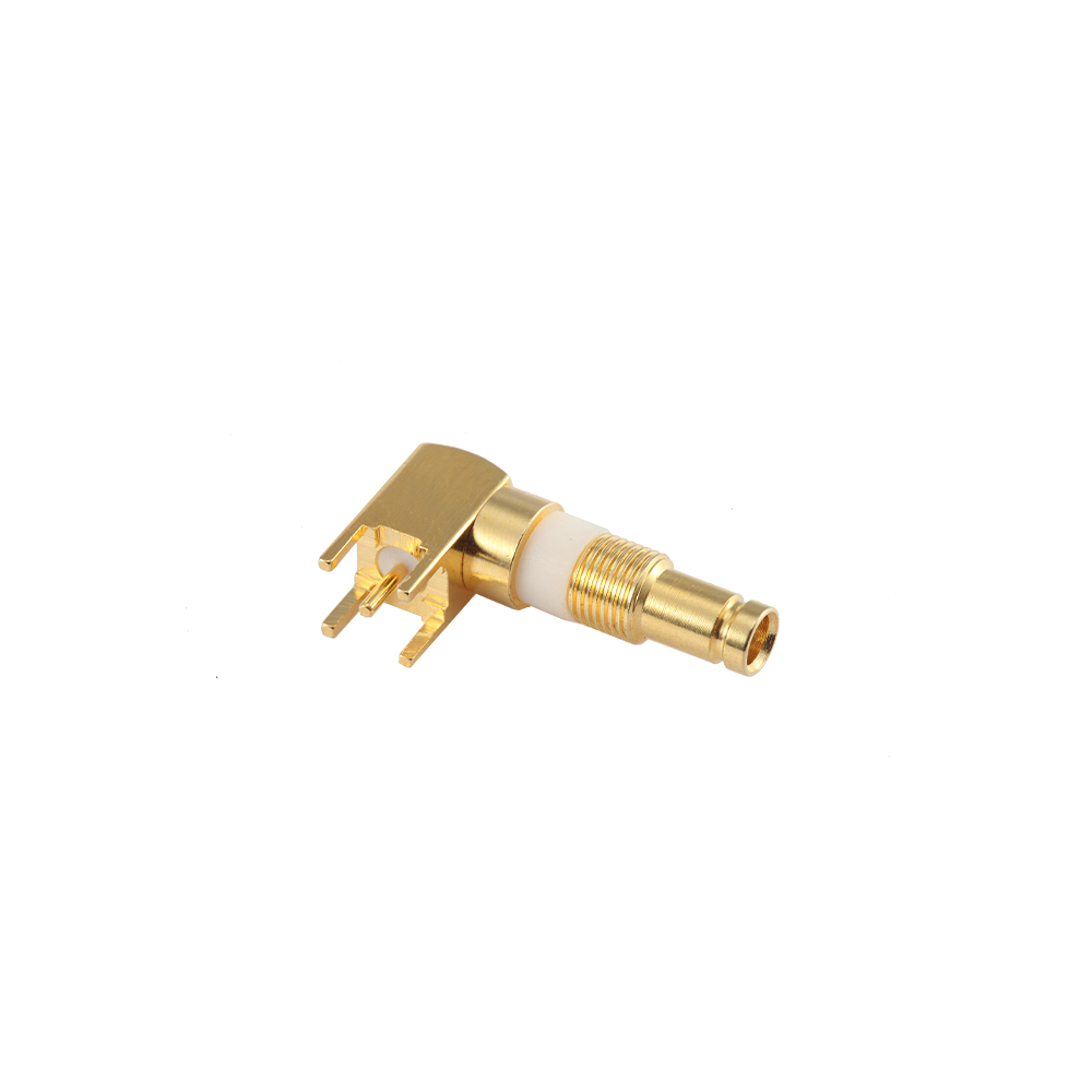
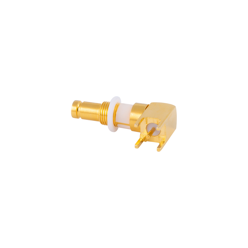
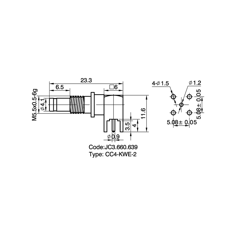
1.0/2.3(CC4) PCB Connectors Custom

Home / Products / Coaxial Connectors / 1.0/2.3(CC4) RF Coaxial Connectors / 1.0/2.3(CC4) PCB Connectors

1.0/2.3(CC4) PCB Connectors Manufacturer

Product Overview
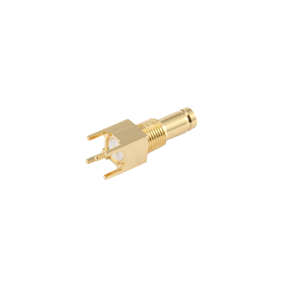
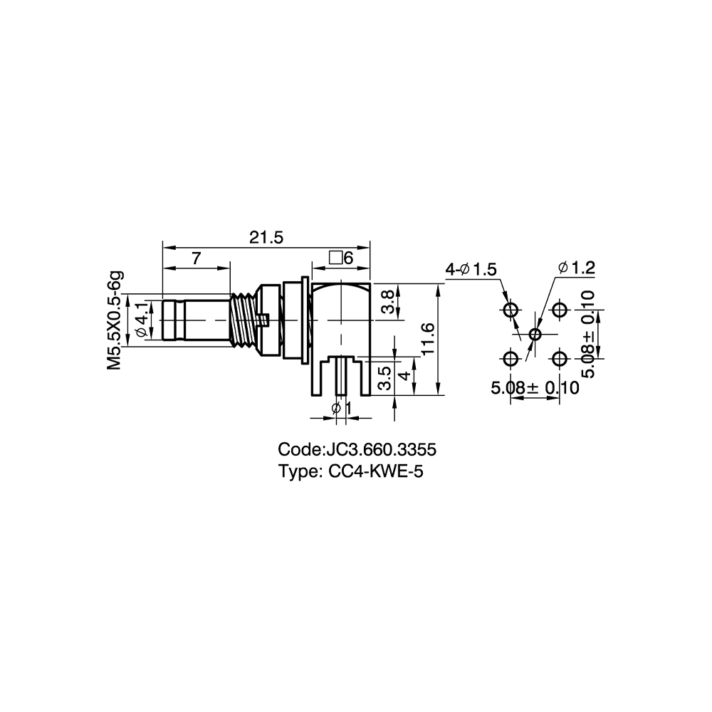
CC4 PCB connectors mount directly to a printed circuit board to provide on-board RF signal I/O. Compared to larger connector series, the CC4 PCB connector occupies a significantly smaller board area, making it well-suited to high-density PCB layouts in compact equipment. Both through-hole (THT) and surface-mount (SMT) variants are available, compatible with wave soldering and reflow processes respectively.

Key Features
Through-hole and SMT options to match different PCB manufacturing processes
Mechanically stable post-soldering; normal mating force does not stress pads
Adequate outer conductor ground pad area for complete RF shielding
Consistent pin pitch and body dimensions compatible with wave and reflow soldering

Competitive Advantages
CNC-machined for tight tolerances and high lot-to-lot consistency, reducing SMT placement defects
Engineering samples available for PCB design-in validation before volume purchase
Footprint and mounting height customization available for OEM board designs

Typical Applications
RF ports on miniaturized wireless communication modules
Signal interfaces on digital distribution device main boards
RF I/O on industrial data acquisition cards
Test instrument PCB RF interfaces

FAQ
Q: Is SMT mounting data (footprint, 3D model) available?
A: Yes. Pin layout drawings and package dimension data are available for SMT models; 3D models are available for select types. Contact the sales team to request the relevant files.
Q: How many mating cycles can CC4 PCB connectors withstand?
A: Mechanical mating life depends on the specific model. Please contact our technical team for the rated mating cycle count for the model you are evaluating.
Q: Can mounting height or pin pitch be customized?
A: Yes. Please provide your PCB layout file or dimensional requirements; our engineering team will assess feasibility and provide a quotation.
Q: Will standard reflow soldering temperatures affect the connector?
A: Standard CC4 PCB connectors use materials and plating compatible with typical reflow profiles. If your process has special temperature requirements, please specify them when inquiring.
Q: What is the minimum order quantity?
A: MOQ varies by model. Please contact the sales team — samples and small-batch orders are supported.
Q: Are both 50 Ohm and 75 Ohm impedances available?
A: Yes. CC4 PCB connectors are offered in both 50 Ohm and 75 Ohm versions. Please specify the required impedance when placing your order.
About
Yangzhou Jingcheng Electronics Co., Ltd.

Yangzhou Jingcheng Electronics Co., Ltd., a premier China 1.0/2.3(CC4) PCB Connectors Manufacturer and 1.0/2.3(CC4) PCB Connectors Supplier, was founded in 1999. It is a high-tech enterprise specializing in the R&D and manufacturing of RF coaxial connectors, cable assemblies, and passive microwave components.
Equipped with a comprehensive R&D and production system, the company has obtained international certifications including ISO9001. Adhering strictly to standards such as MIL, IEC and GB, we offer over 30 product series with more than 2,000 specifications, covering SMA, BNC, N-type and other mainstream models. Our products are widely applied in the fields of communications, aerospace, automotive electronics and beyond, and exported to many countries and regions across Europe, America and Asia.
We uphold the tenet of "Quality as the Foundation, Customers as the Core", committed to providing reliable interconnection solutions and professional services for global clients.

1.0/2.3(CC4) PCB Connectors Industry knowledge

1.0/2.3 (CC4) PCB connectors are board-mount RF coaxial connectors that transfer signal directly between a printed circuit board and a mating cable, blind-mate module, or adjacent board. Unlike cable-to-cable versions of the series, 1.0/2.3 (CC4) PCB connectors are soldered or press-fit onto the board using SMT pads or through-hole legs, with the center contact aligned to the board's RF trace and the outer shell grounded to the surrounding copper plane. This mounting method keeps the coaxial structure, and its 50Ω impedance, continuous from the board trace into the connector body.

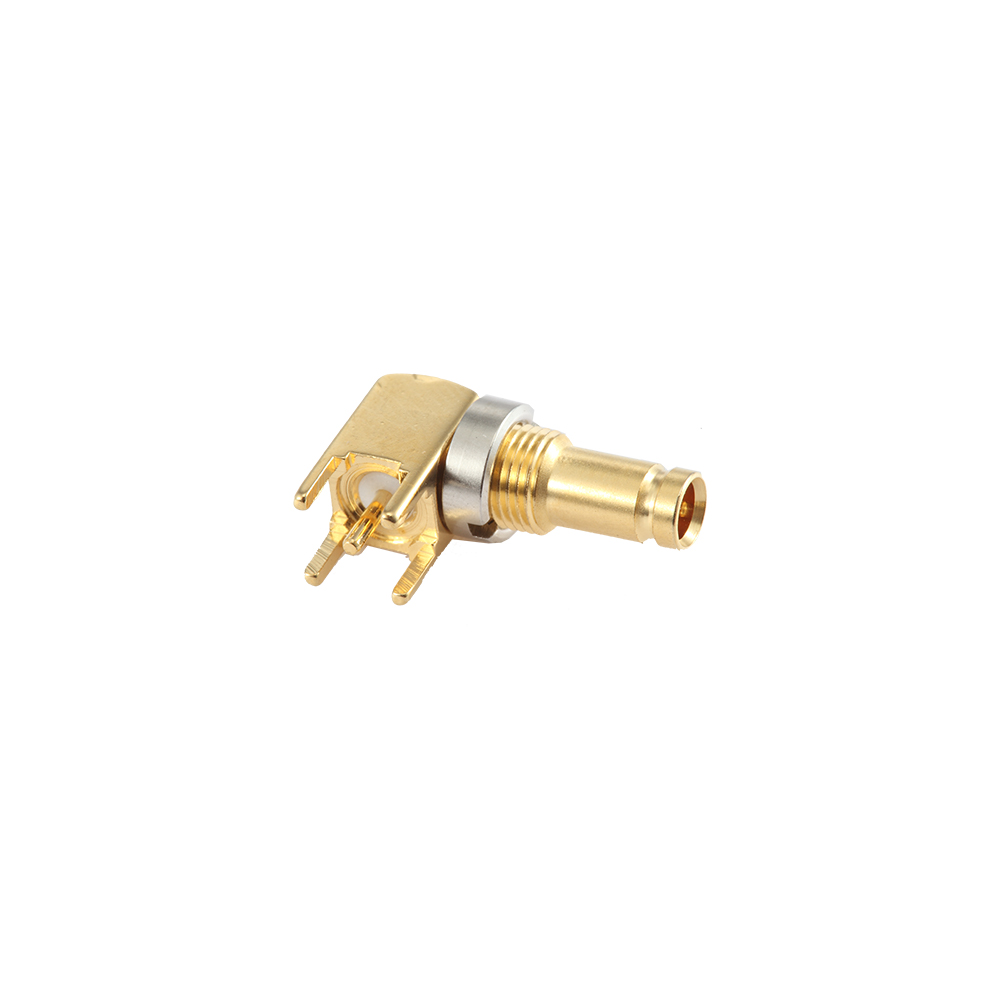
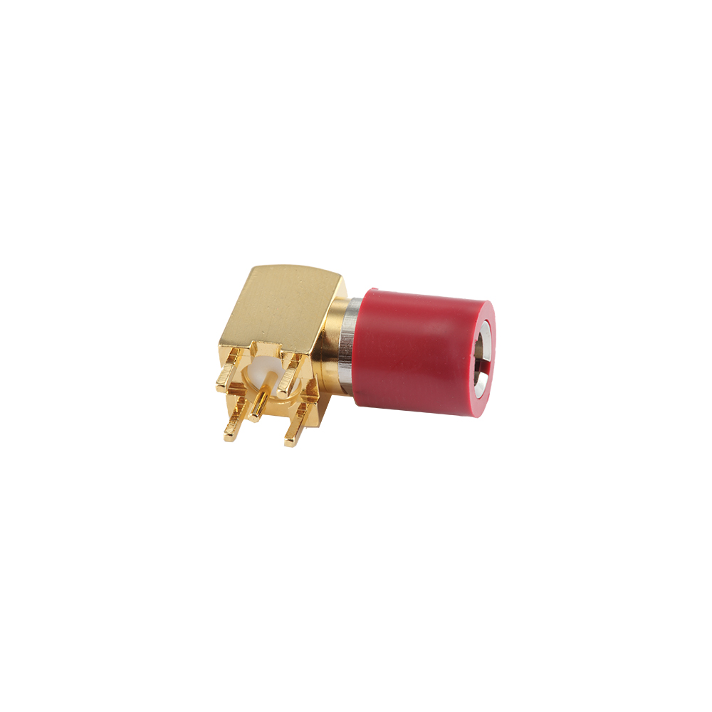
Vertical, right-angle, and edge-launch orientations are all available within the 1.0/2.3 (CC4) PCB connectors range, allowing the mating axis to be set parallel or perpendicular to the board depending on the enclosure layout.

Pitch & Pin Count

Each connector carries a single coaxial signal path, so pin count refers to one center contact plus its grounded shell rather than a multi-pin header. Where several ports are placed on one panel, such as blind-mate board-to-board arrays, center-to-center pitch is commonly set at 3.0mm to 4.5mm, sized to clear neighboring shells while keeping the module footprint compact.

  • Footprint pad diameter matched to the board's plated through-hole or SMT land pattern
  • Ground leg spacing aligned to the board's via fence for shielding continuity
  • Array pitch confirmed against board layout before panel tooling is finalized

Electrical Specifications

1.0/2.3 (CC4) PCB connectors hold a 50Ω characteristic impedance across DC to 11GHz, with insertion loss and VSWR figures close to their cable-mount counterparts when the board trace is properly matched. Contact resistance and dielectric withstanding voltage are held within standard limits to support repeated mating cycles in production and field service.

Typical electrical specifications of 1.0/2.3 (CC4) PCB connectors
Parameter Typical Value
Impedance 50Ω
Frequency range DC–11GHz
Contact resistance ≤3mΩ
Dielectric withstanding voltage 500V RMS

Application

The compact mounting profile of 1.0/2.3 (CC4) PCB connectors suits RF modules where board space is limited and multiple signal paths sit close together.

  • Base station and small cell RF module boards
  • Blind-mate board-to-board connections in filter and duplexer assemblies
  • Compact test fixtures and RF instrumentation boards
  • Onboard connections in vehicle and industrial communication modules

Yangzhou Jingcheng Electronics Co., Ltd manufactures 1.0/2.3 (CC4) PCB connectors and matched cable assemblies under MIL, IEC, and GB standards, supplying communication and RF module producers across multiple regions.

Customization

Board layout and enclosure geometry vary between projects, so several attributes of the connector can be adjusted to fit a specific design.

  • Mounting style: SMT, through-hole, or press-fit
  • Orientation: vertical, right-angle, or edge-launch
  • Plating: gold or nickel finish on contact and shell surfaces
  • Array pitch and port count matched to a specific board layout

Comparison with Other PCB Connector Types

Comparison of 1.0/2.3 (CC4) PCB connectors with other miniature PCB-mount RF connector types
Parameter 1.0/2.3 (CC4) Type A Type B
Mating style Threaded Push-on Push-on
Frequency range DC–11GHz DC–6GHz DC–8GHz
Board footprint Compact Smaller Compact
Typical use Base station modules Portable devices Test fixtures

The threaded mating interface gives 1.0/2.3 (CC4) PCB connectors a retention advantage over push-on types in equipment subject to vibration, at the cost of a slightly larger board footprint.

Maintenance Guidance

  1. Inspect solder joints for cracks or cold solder after reflow, particularly on ground legs carrying the shielding path.
  2. Apply mating force along the connector axis to avoid stressing the solder joint during cable insertion or removal.
  3. Check board-side trace continuity with a network analyzer if insertion loss increases over time.
  4. Keep contact surfaces free of flux residue, which can raise contact resistance at the mating interface.
  5. Fit a dust cap on unused ports during board handling and storage to protect the center contact.

Frequently Asked Questions

Can 1.0/2.3 (CC4) PCB connectors be reflow soldered?

SMT variants are designed for standard reflow profiles, while through-hole and press-fit variants are suited to wave soldering or manual assembly.

How is board layout matched to the connector footprint?

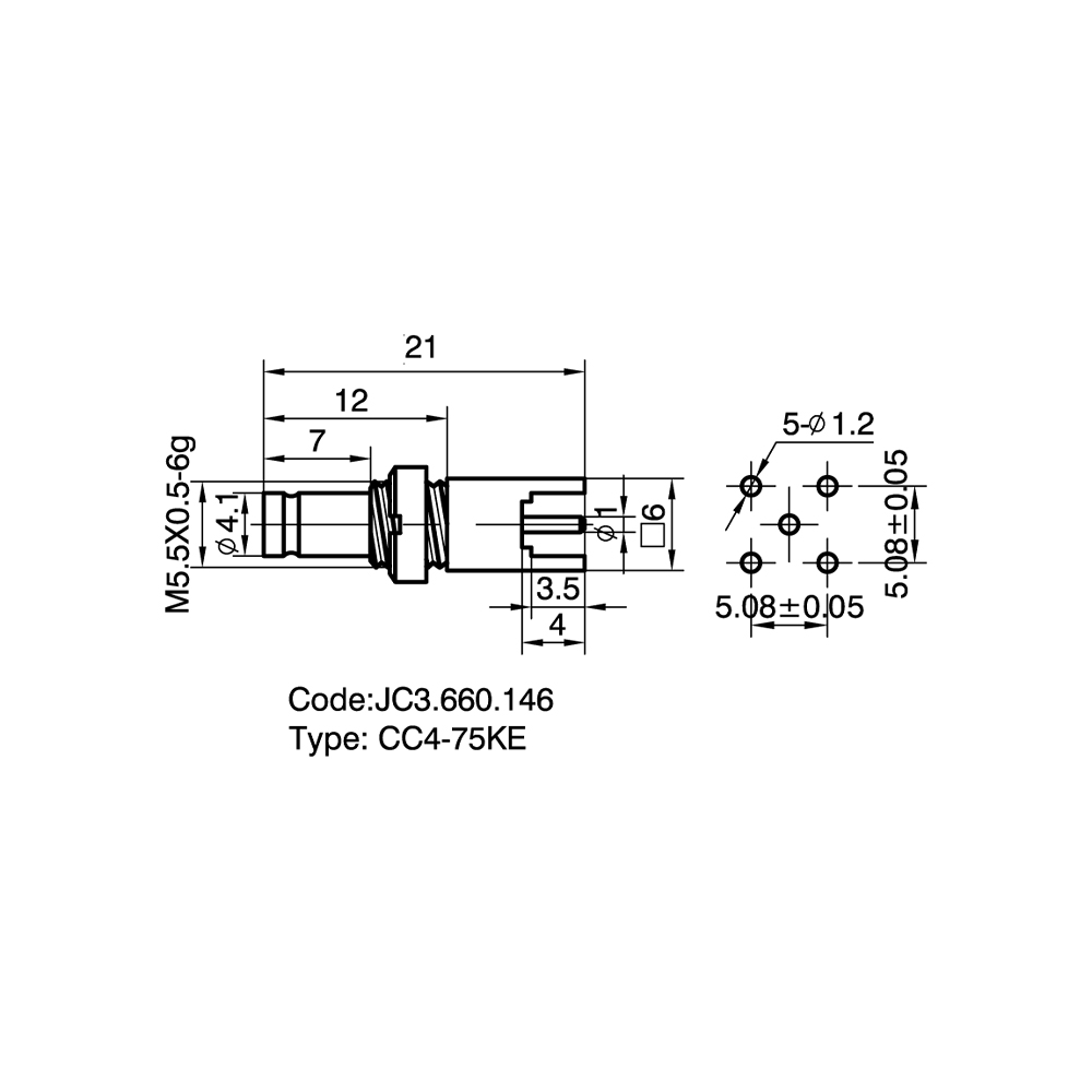
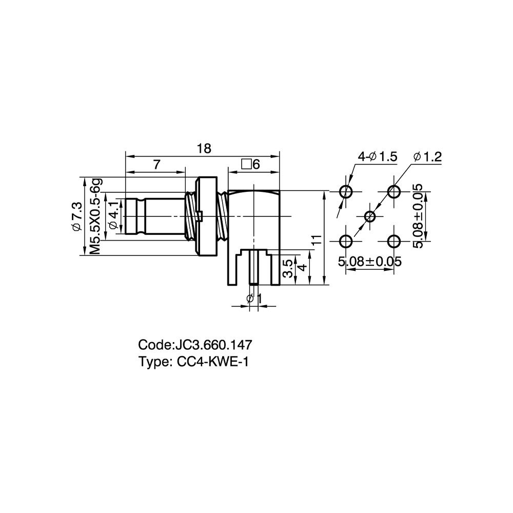
The board's trace width, via fence spacing, and pad pattern should follow the connector's mounting drawing to keep the 50Ω path continuous from the board into the connector.

Can pitch and port count be customized for a multi-port panel?

Array pitch and port count can be configured to a specific board layout, based on the equipment interface drawing or an existing board sample.