F PCB Connectors Custom

Home / Products / Coaxial Connectors / F RF Coaxial Connectors / F PCB Connectors

F PCB Connectors Manufacturer

Product Overview
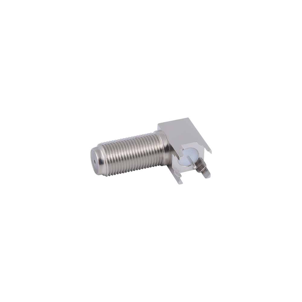
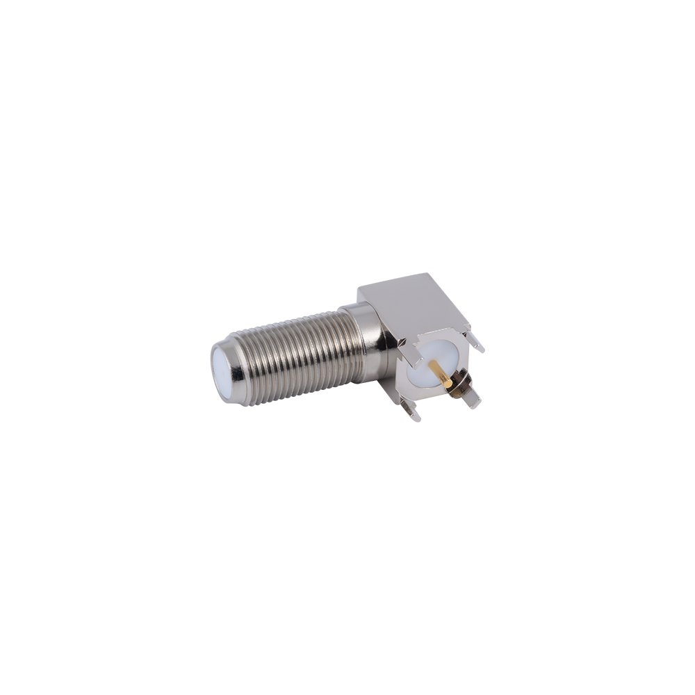
F-type PCB connectors are soldered directly onto the circuit board—available in both through-hole and surface-mount configurations—eliminating the need for separate panel-mount jacks and pigtail cables, and bringing the F-type coaxial interface directly to the board. For cable TV equipment and consumer electronics RF inputs, the direct board-mount solution saves assembly steps and reduces costs, while also eliminating one cable connection point and improving overall reliability.
F-type PCB connectors are commonly found on set-top box mainboards, optical modem PCBs, residential gateway boards, and TV tuner modules—they are used in any product that requires receiving F-type coaxial signals directly from home cable TV wiring.

Key Features
Available in both through-hole and SMT (surface mount, reflow solder compatible) options to accommodate different PCB assembly processes.
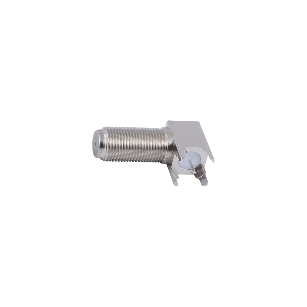
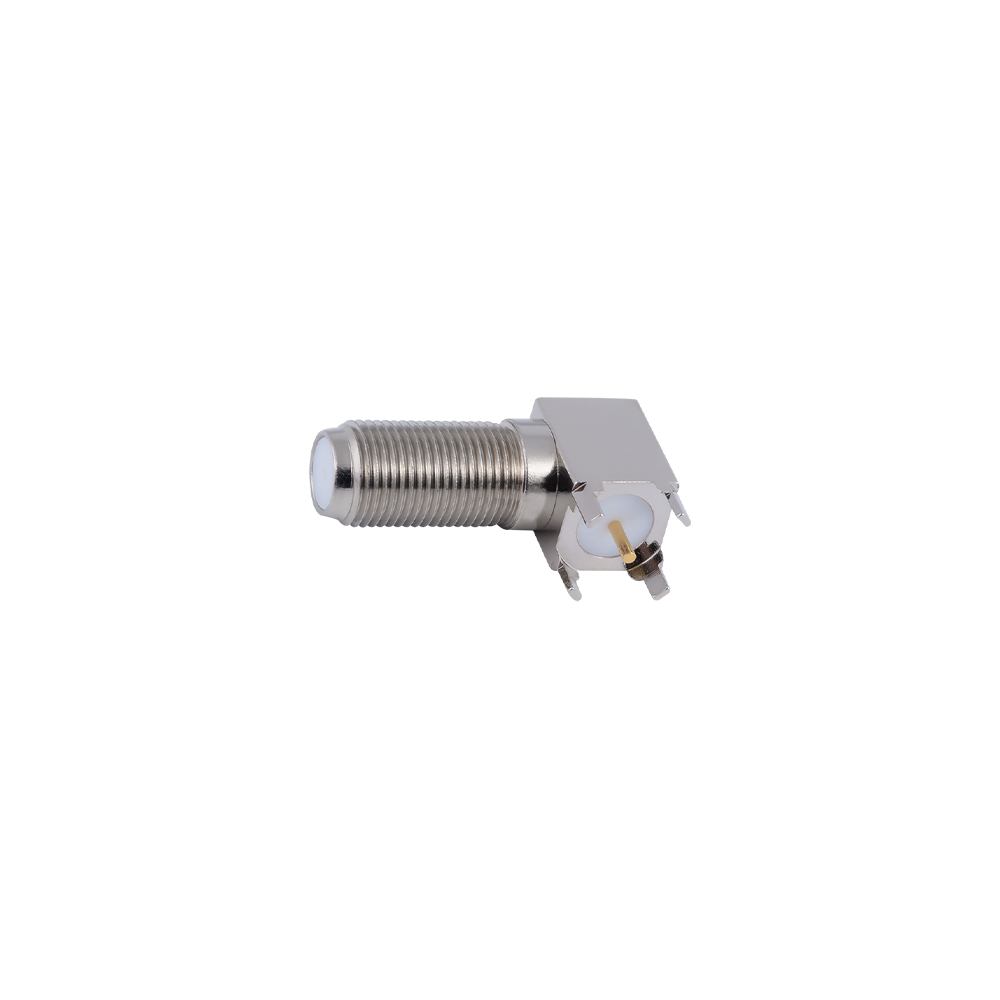
Right-angle (horizontal) orientation, allowing cables to exit cleanly from the edge of the board and align naturally with the device’s rear panel.
75Ω characteristic impedance, matched to standard cable TV and satellite TV signal sources.
RoHS compliant and lead-free solder compatible, requiring no adjustments to manufacturing line process parameters.
PCB footprint dimensions follow standard packaging, allowing for direct integration into existing PCB designs.

Competitive Advantages
RF input interface for set-top boxes and smart TVs
RF input for optical modems and residential gateways
CATV distribution amplifier and splitter module PCBs
Satellite receiver module tuner input connections
Terrestrial digital television (DTT) receiver PCBs

FAQ
Q: What is the difference between an F-type PCB connector and an F-type microstrip connector?
A: An F-type PCB connector has a fixed center contact pin; when a user inserts an F-type cable, the cable's center conductor presses against this contact pin to establish conductivity—this is an interface intended for user-operated cable plugging. In contrast, a microstrip connector features contact elements that press directly onto the PCB traces; these are intended for test fixtures and internal module connections, and are not designed for user-operated cable plugging.
Q: Can you provide 3D STEP models and PCB footprint data?
A: Yes. Dimensional drawings and standard PCB footprint data are provided with the product datasheet, and 3D STEP models can be provided upon request.
Q: Is the SMT version compatible with standard lead-free reflow soldering processes?
A: Yes, it is. All SMT versions are designed in accordance with IPC/JEDEC lead-free reflow soldering standards (peak temperature of 260°C), with connector housing and dielectric materials that maintain dimensional stability during the reflow process.

About
Yangzhou Jingcheng Electronics Co., Ltd.

Yangzhou Jingcheng Electronics Co., Ltd., a premier China F PCB Connectors Manufacturer and F PCB Connectors Supplier, was founded in 1999. It is a high-tech enterprise specializing in the R&D and manufacturing of RF coaxial connectors, cable assemblies, and passive microwave components.
Equipped with a comprehensive R&D and production system, the company has obtained international certifications including ISO9001. Adhering strictly to standards such as MIL, IEC and GB, we offer over 30 product series with more than 2,000 specifications, covering SMA, BNC, N-type and other mainstream models. Our products are widely applied in the fields of communications, aerospace, automotive electronics and beyond, and exported to many countries and regions across Europe, America and Asia.
We uphold the tenet of "Quality as the Foundation, Customers as the Core", committed to providing reliable interconnection solutions and professional services for global clients.

F PCB Connectors Industry knowledge

F PCB connectors are board-mount versions of the F connector interface, built for permanent installation on a printed circuit board rather than termination onto cable. Each connector keeps the threaded, screw-on coupling of the standard F interface on the mating side, while the board-facing end is formed with solder legs, a through-hole shell, or a flange that fixes the connector position and orientation on the board.

Because the center contact is soldered to a board pad or trace rather than relying on the cable core as the mating pin, F PCB connectors give equipment designers a fixed, repeatable 75 Ω transition point between an internal circuit and an external coaxial cable.

Common Types and Characteristics

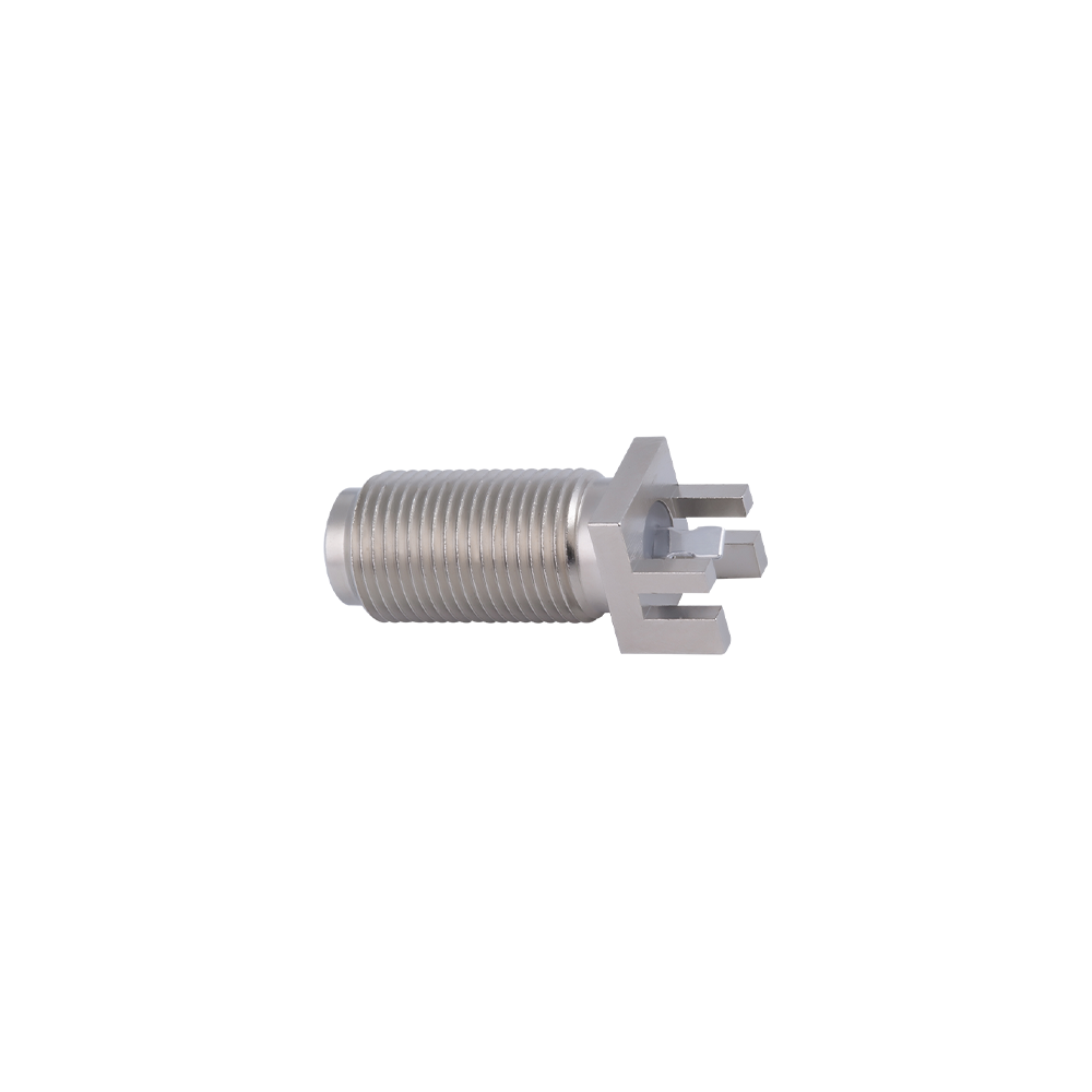
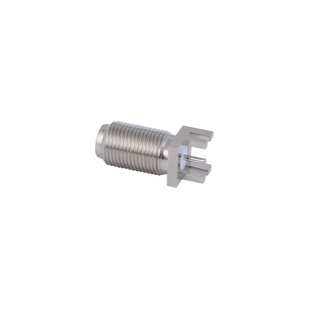
  • Vertical through-hole mount connectors — mounted perpendicular to the board for panel-facing cable connections at an enclosure edge.
  • Right-angle mount connectors — mounted parallel to the board surface, used where enclosure height is limited.
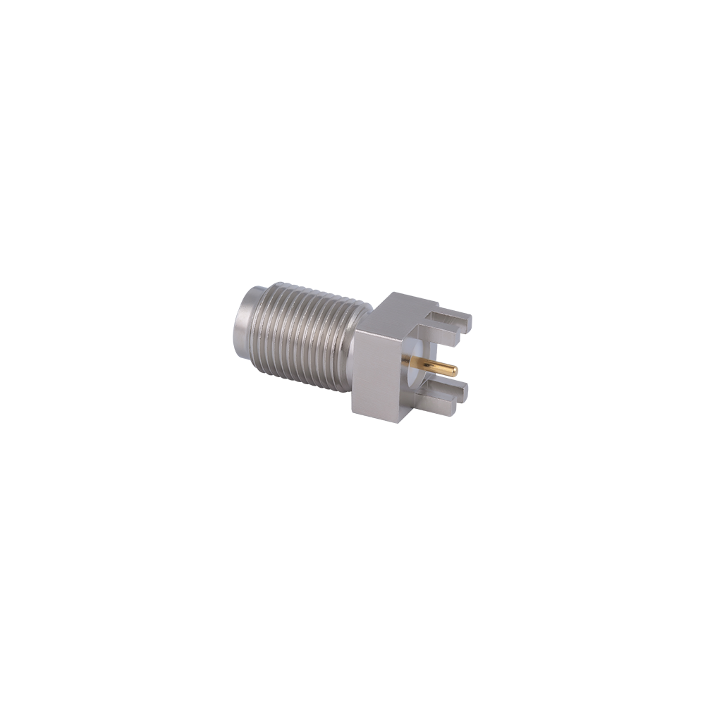
  • Micro-strip edge-launch connectors — positioned at the board edge with the center contact aligned to a micro-strip transmission line for a short, low-loss transition.
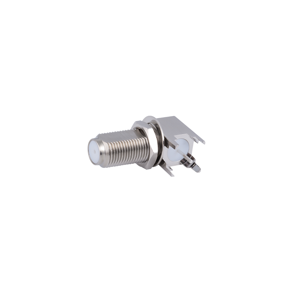
  • Panel-and-board combination connectors — combine a flange for chassis fixing with solder legs for board connection, used where both mechanical support and board contact are needed.

Core Performance Parameters

Typical electrical and mechanical specifications
Parameter Typical Value
Impedance 75 Ω
Frequency Range DC – 3 GHz
Coupling Type Threaded, screw-on
Mounting Style Through-hole, right-angle, or edge-launch
Mating Cycles ≥ 500

Typical Applications

The fixed board interface of F PCB connectors is applied wherever equipment needs a consistent connection point between an internal circuit board and an external coaxial cable.

  • Set-top box and digital terrestrial (DVB-T) tuner circuit boards
  • Cable modem and broadband gateway RF front-end modules
  • Satellite receiver internal tuner and distribution boards
  • Signal amplifier, splitter, and video distribution circuit assemblies

Comparison with Cable Mount F Connectors

Compared with crimp or compression F connectors used on cable, F PCB connectors terminate to a board pad or trace instead of a cable core, which fixes the connector position permanently on the board and requires a soldering process during assembly rather than field crimping or compression tools.

Comparison of termination point, assembly method and typical use
Connector Type Termination Point Assembly Method Typical Use
F PCB connector Board pad or trace Soldering Internal board-to-cable transition
Crimp F connector Cable core and braid Crimping tool Indoor cable wiring
Compression F connector Cable core and jacket Compression tool Outdoor cable runs

Selection Guide

  1. Choose vertical, right-angle, or edge-launch mounting based on available enclosure height and board orientation.
  2. Match the solder leg spacing and footprint to the existing board layout to avoid trace rerouting.
  3. Select an edge-launch design where a short, low-loss transition to a micro-strip line is required for higher-frequency signals.
  4. Choose a panel-and-board combination connector where both chassis fixing and board contact are needed in the same part.
  5. Confirm solder pad plating is compatible with the board assembly process, including reflow or hand soldering requirements.

Frequently Asked Questions

What is the difference between F PCB connectors and F micro-strip connectors?

F micro-strip connectors are one mounting style within the broader F PCB connector category, specifically aligned to a micro-strip transmission line at the board edge, while F PCB connectors as a category also include through-hole, right-angle, and panel-combination mounting styles.

Can F PCB connectors be reflow soldered?

Surface-mount variants are generally compatible with reflow processes, while through-hole variants are more commonly wave or hand soldered; the specific part datasheet should be checked.

Are F PCB connectors compatible with standard F-type cable plugs?

Yes, the mating thread and center contact follow the same F interface, so standard cable-mounted F plugs mate directly with any board-mounted jack in this category.

Manufacturing Background

Yangzhou Jingcheng Electronics Co., Ltd. produces F PCB connectors along with a broad range of RF connector series including SMA, BNC, TNC, N-type, and reverse polarity variants, together with high-frequency cable assemblies covering 0 to 50 GHz. Manufacturing follows ISO9001 quality management and MIL, IEC, and GB reference standards, supporting broadcast, broadband, and consumer electronics equipment.