English
 中文简体
中文简体
A 50 ohm BNC connector is built for 50 ohm systems, and a 75 ohm BNC connector is built for 75 ohm systems. The two always fit each other mechanically — same bayonet shell, same coupling lugs, same pin arrangement — but they are not electrically equivalent: the characteristic impedance each connector maintains is different, and the intended applications are different. Choose 50 ohm for RF, telecom, and test equipment; choose 75 ohm for video, broadcast, and surveillance links.
At baseband video frequencies, a mismatched BNC junction may only produce a faint ghost. On an RF transmitter or an HD-SDI link, the same junction raises VSWR and closes the eye pattern. This article compares the two connector types, shows what happens when they meet, and explains how to choose the right part.
Content
What the Impedance Number Means
The number on a BNC connector is the characteristic impedance of the transmission-line path it maintains. A connector of the wrong impedance acts as a small discontinuity: part of the signal passes through, and part reflects back toward the source.
Characteristic impedance is the ratio of the voltage wave to the current wave traveling down a uniform line. It is set by the ratio of the outer conductor diameter to the inner conductor diameter and by the dielectric between them. Cable length does not change it, and neither does the position of a switch.
Why 50 Ω became the RF standard
Fifty ohms is a compromise. The theoretical optimum impedance for maximum power handling is near 30 ohms, and the optimum for minimum attenuation is near 77 ohms. A 50 ohm system gives up a little on both curves and keeps the best overall balance, which is why it dominates radio, cellular infrastructure, GPS, Wi-Fi backhaul, and RF test equipment.
Why 75 Ω became the video standard
Seventy-five ohms sits close to the minimum-attenuation point, so it delivers the longest cable run before amplification is needed. That property made it the natural choice for analog video, broadcast, CCTV, and cable television, and the convention carried over to digital video and SDI. A 50 ohm BNC connector is rated to roughly 4 GHz in typical RF use, while 75 ohm BNC parts are almost always used well below 1 GHz, where the BNC shell size still behaves cleanly.
Construction Differences Between 50 Ω and 75 Ω BNC Connectors
Externally the two BNC types look identical and share the same shell, bayonet, and mating dimensions. The differences are inside: the dielectric geometry and the center contact.
A coaxial connector has to preserve the conductor ratio and the dielectric environment of the cable it terminates. Because the BNC shell is standardized, the center contact and the insulator carry the impedance. A 50 Ω BNC plug uses solid PTFE insulation, and its center pin protrudes beyond the dielectric face so it can be gripped. A 75 Ω BNC plug uses a modified dielectric profile — often air-spaced or webbed — and its center pin is recessed below the dielectric nose, which makes the part touch-proof. This recessed pin is a deliberate design of the 75 Ω BNC standard, not a manufacturing accident.
| Characteristic | 50 Ω BNC | 75 Ω BNC |
|---|---|---|
| Impedance | 50 ohms | 75 ohms |
| Reference standard | MIL-STD-348, IEC 60169-8 | IEC 60169-12, EN 122190 |
| Dielectric | Solid PTFE | Air-spaced or webbed dielectric |
| Center contact | Protruding, touchable | Recessed, touch-proof |
| Typical cable | RG-58, RG-213 | RG-59, RG-6 |
| Typical application | RF, telecom, test, GPS | Video, SDI, CCTV, CATV |
When you assemble a cable, match the connector impedance to the cable impedance before you match the connector to the cable diameter. A 50 Ω BNC designed for flexible cable, crimped onto RG-58, is the standard RF jumper; a 75 Ω BNC crimped onto RG-59 is the video equivalent.
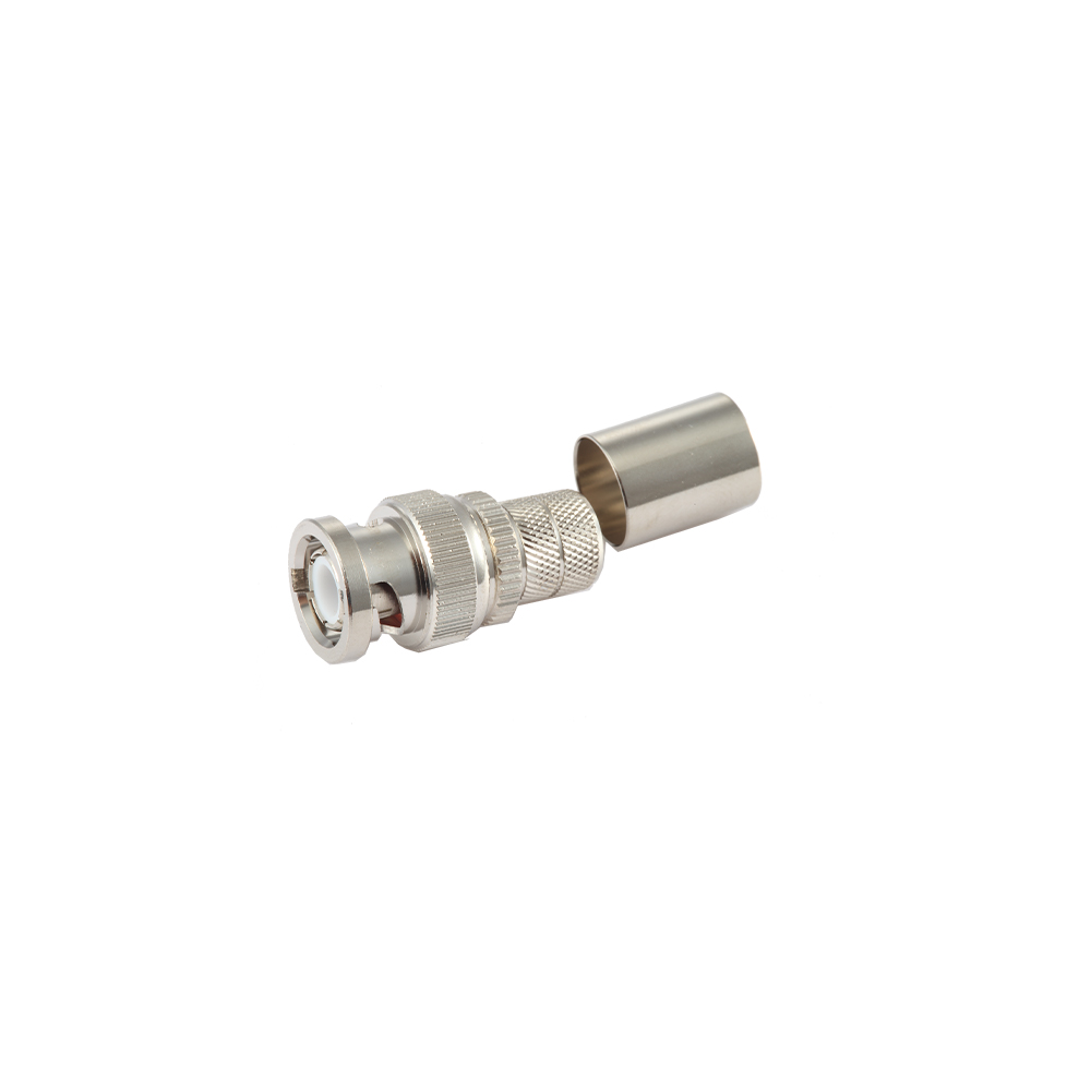 BNC Connectors for Flexible Coaxial Cables with Matched ImpedanceThis connector family terminates RG-58, RG-59, and similar flexible cables with controlled center-pin geometry, helping maintain the intended 50 or 75 ohm impedance through the junction and minimize reflections in the assembled cable.View Product →
Can You Mix 50 Ω and 75 Ω BNC Connectors?
You can — the bayonet locks firmly — but the result is a small impedance step that reflects part of the signal. If a 75 Ω video path contains a 50 Ω connector, the reflection coefficient at the junction is (50 − 75) ÷ (50 + 75) = −0.20: about 20 percent of the voltage wave sees a discontinuity. The VSWR is 1.50:1, the return loss is close to 14 dB, and about 4 percent of the power bounces back.
| Metric | Value for a 50 Ω connector on a 75 Ω path |
|---|---|
| Reflection coefficient | 0.20 |
| VSWR | 1.50:1 |
| Return loss | About 14 dB |
| Reflected power | 4 percent |
Whether those numbers matter depends on frequency and bit rate. At baseband video up to a few megahertz, the wavelength is tens of meters, so a centimeter-sized connector mismatch may be invisible or show up as a faint echo. On an HD-SDI link at 1.485 Gbit/s and beyond, the same junction costs data margin and can cause picture dropouts or loss of lock. In an RF test setup, any wrong-impedance adapter, barrel, or connector corrupts calibration; in a transmitter chain, the reflected power changes what the output stage sees and can trip protective circuits.
Instrumentation and test boards should keep the impedance reference intact from the board to the cable. A PCB-mount 50 Ω BNC with a short, well-shaped ground transition preserves that reference at the point where the signal enters or leaves the board.
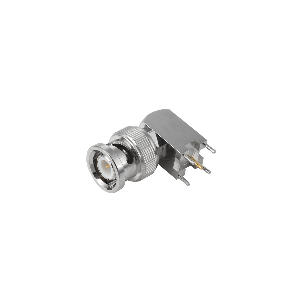 PCB-Mount BNC Connectors for Board-Level Signal IntegrityDirect board-mount BNCs preserve the impedance reference at the PCB transition, making them suitable for test boards and instrumentation where a short, controlled launch into the circuit is needed.View Product →
How to Identify a 50 Ω or 75 Ω BNC Connector
The fastest check is visual: look at the mating face of a plug. A protruding center pin surrounded by solid PTFE means 50 Ω. A recessed center pin hidden below a dielectric nose means 75 Ω.
- Plug face: pin exposed = 50 Ω; pin recessed and touch-proof = 75 Ω.
- Body and boot markings: many parts are stamped “50 Ω”, “75 Ω”, or with a specific series; a plain “BNC” marking does not prove the impedance.
- Cable jacket: RG-58 and RG-213 are 50 Ω; RG-59 and RG-6 are 75 Ω — but check the marking on the cable, because connectors can be fitted onto the wrong cable.
- Measurement: a time-domain reflectometer or a network analyzer gives a definitive value when the application cannot tolerate doubt.
- Adapters: a BNC within-type adapter couples two connectors mechanically; it does not convert impedance. Using one only moves the junction.
Treat parts stamped “50/75 Ω” with suspicion. Some utility connectors carry both ratings because they are intended for low-frequency control or video links with loose requirements. In a broadcast or precision RF system, that kind of part is not a substitute for a true 50 Ω or true 75 Ω component.
How to Choose the Right BNC Connector Impedance
Decide the system impedance first, then select the cable, the connector termination, and the mounting style to match. The impedance must be consistent from the equipment port to the far end of the cable.
- Identify the system impedance from the equipment datasheet or port label. RF instruments, radios, GPS receivers, and most antennas are 50 Ω. Cameras, video routers, monitors, and SDI gear are 75 Ω.
- Select cable of the same impedance. Use RG-58 or RG-213 for 50 Ω; RG-59 or RG-6 for 75 Ω.
- Match the termination to the cable. Crimp connectors suit volume production, clamp and solder types suit field repair; never force a connector body designed for one cable diameter onto another.
- Choose the mounting style. Flexible-cable connectors make jumpers, bulkhead connectors terminate panels and chassis, PCB connectors land on circuit boards, and flange connectors bolt to a flat surface.
- Check the VSWR or return-loss specification if the frequency is high or the run is long. For 50 Ω RF work, a 1.30:1 VSWR at the operating frequency is a reasonable target; for video, the connector should state 75 Ω with an explicit frequency limit.
If you are deciding between BNC and other families, the RF coaxial connector selection guide explains how BNC compares with TNC, N, SMA, and related series, and which electrical parameters matter most.
Where a cable enters a chassis, use a bulkhead-mount connector so the shield bonds directly to the panel and the cable is mechanically relieved. That keeps the impedance transition short and prevents strain on the solder or crimp point.
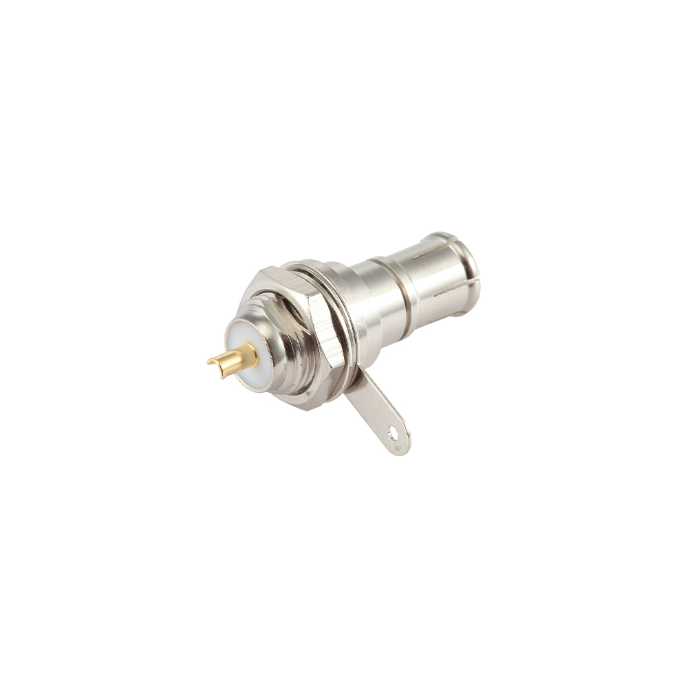 Bulkhead-Mount BNC Connectors for Chassis and Panel FeedthroughSingle-hole panel-mount BNCs bond the shield directly to the chassis, providing mechanical strain relief and a compact feedthrough that keeps the impedance path short when routing cables through enclosure walls.View Product →
Frequently Asked Questions
Is a 50 Ω BNC physically compatible with a 75 Ω BNC?
Yes. The shell diameter, bayonet lugs, and center-pin diameter are the same, so a 50 Ω plug locks firmly into a 75 Ω jack and vice versa. The compatibility is mechanical only; the electrical impedance still differs.
Can mixing 50 Ω and 75 Ω BNC connectors damage equipment?
Not directly. The junction reflects a few percent of the signal power, which is usually absorbed by the cable and the connectors. The practical risks are reduced video margin, RF calibration errors, and transmitter VSWR protection tripping on high-power links.
How can I tell whether my cable is 50 Ω or 75 Ω?
Read the jacket marking if it is legible: RG-58 and RG-213 are 50 Ω; RG-59 and RG-6 are 75 Ω. When the marking is missing, verify the connector geometry or measure the line if the application needs an impedance budget.
Why is the 75 Ω BNC center pin recessed?
The recessed, touch-proof center contact is part of the 75 Ω BNC design. It prevents the user from touching a live pin while patching broadcast or video racks, and it reduces the chance of an accidental short to the shell.
Do I need 75 Ω BNC connectors for SDI video?
Yes. SDI is a 75 Ω standard end to end. A 50 Ω connector inserted anywhere in the path adds a reflection at the serial data rate; short test patches may pass, but production links should remain all 75 Ω.