News

Home / News / Industry News / BNC Connector Sizes Explained: Dimensions, 50Ω vs 75Ω, and Cable Types

BNC Connector Sizes Explained: Dimensions, 50Ω vs 75Ω, and Cable Types


Yangzhou Jingcheng Electronics Co., Ltd. is professional in designing, developing, producing, sales and service of RF (Radio Frequency) coaxial connectors.

BNC connectors are not one-size-fits-all components. The practical "size" of a BNC connector is defined by two separate characteristics: the mating interface and the center conductor. Every standard BNC shares the same bayonet shell diameter—roughly 14.5 mm on the plug—so any BNC plug will click onto any BNC jack. What really differs is the center pin: a 50-ohm BNC uses a thicker pin of about 1.3 mm, while a 75-ohm BNC uses a thinner pin of about 1.0 mm.

That is why a 75-ohm BNC cable will still fit into a 50-ohm instrument port. It will also degrade the measurement: the impedance mismatch creates reflections at the junction, raising VSWR and attenuating the signal. Size, therefore, is not just a mechanical dimension—it is an electrical one. This article explains the interface dimensions, impedance variants, compatible cable sizes, and practical steps for choosing the correct BNC for your project. For a broader introduction to coaxial interfaces, see our RF coaxial connector guide.

BNC Connector Interface Dimensions: What "Size" Really Means

The term "size" can refer to three different dimensions on a BNC connector, and confusing them causes most selection errors.

  • Mating interface dimension—the outside shell and coupling geometry, which are standardized and identical for all compliant BNC connectors.
  • Center pin dimension—the diameter of the male pin, which changes with nominal impedance (50 ohm vs 75 ohm).
  • Cable entry dimension—the rear barrel diameter and clamping range, which must match the coaxial cable's dielectric and outer jacket.

For the mating interface itself, the key values are the plug shell outer diameter of about 0.570 in (14.5 mm), the jack shell diameter of about 0.436 in (11.1 mm), and the 1/4-turn bayonet lock that holds the two halves together. Both 50-ohm and 75-ohm versions share this shell geometry, which is exactly why the two are mechanically interchangeable even though they are electrically different.

Key differences between 50-ohm and 75-ohm BNC connectors
Parameter 50-ohm BNC 75-ohm BNC
Center pin diameter (male) Approx. 1.3 mm (0.051 in) Approx. 1.0 mm (0.039 in)
Dielectric position Recessed behind the mating face Nearly flush with the mating face
Typical frequency range Up to 4 GHz Up to 1–2 GHz depending on design
Primary applications Test instruments, RF transmission, wireless equipment CCTV, video broadcasting, base station video links
Result of mixing with wrong system Impedance mismatch, reflected signal, higher VSWR Same as left, plus faster contact wear in severe cases

Cable Sizes Compatible with BNC Connectors

BNC connectors are specified by the cable they terminate, not by the BNC name alone. The rear barrel must grip the correct cable diameter, or the joint will loosen under vibration and tension.

Common coaxial cables used with BNC connectors and their typical outer diameters
Cable type Impedance Outer diameter Typical BNC use
RG-58 50 ohm Approx. 5.0 mm Test leads, GPS, short jumpers
RG-174 50 ohm Approx. 2.5 mm Compact internal jumpers, pigtails
RG-213 50 ohm Approx. 10.3 mm High-power radio feeder lines
RG-59 75 ohm Approx. 6.2 mm Analog CCTV, legacy video links
RG-6 75 ohm Approx. 6.9 mm Digital video, broadband, satellite IF

When you order a BNC for a specific cable, confirm that the manufacturer lists a matching clamp range. A connector meant for RG-58 will not seal correctly on RG-6, and the resulting mechanical play can slowly damage the center pin. If you need to transition from one cable size to another, an inline barrel adapter is not the correct fix—match the connector to the cable first.

BNC Body Styles: Cable, Panel, and PCB Mounting

BNC connectors are available in several mechanical body styles, and the mounting style must be decided before you choose a part number. The electrical size matters little if the connector cannot be secured properly in your enclosure.

Cable-style connectors terminate the end of a flexible coaxial cable and are the most common form for test leads, antenna jumpers, and video runs. They use crimp, clamp, or solder attachment to the center conductor and braid, so the cable diameter and the connector barrel must match.
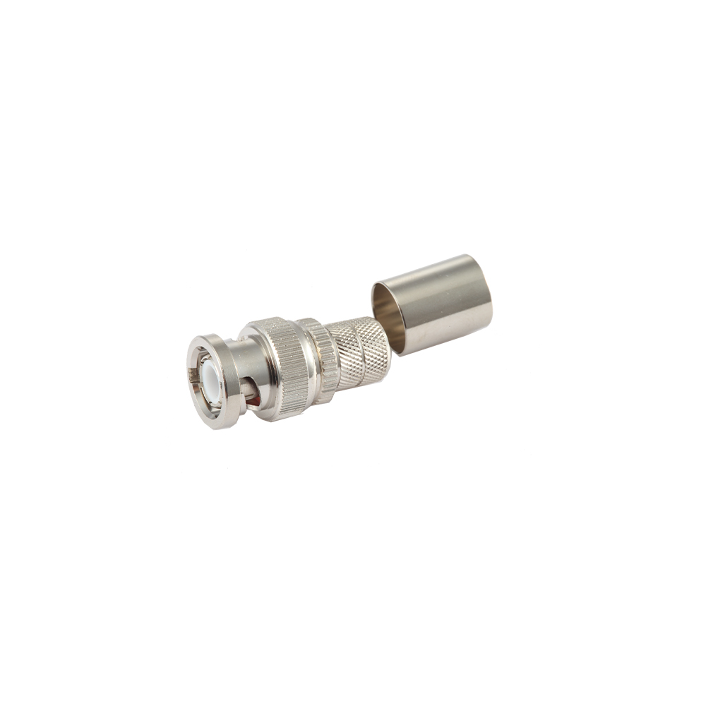
BNC Connectors for Flexible Coaxial CablesBNC Connectors for Flexible Coaxial CablesThis page covers BNC connectors made for flexible RF cables like RG-58 and LMR-200, with crimp, clamp, or solder termination and multiple exit angles for reliable cable assemblies.View Product →

Bulkhead connectors are designed to mount through a panel or chassis, with the mating face on one side and the cable connection on the other. They are the preferred choice when a clean, repeatable front-panel test point is required, because the connector stays fixed while the cable bends and flexes behind the panel.
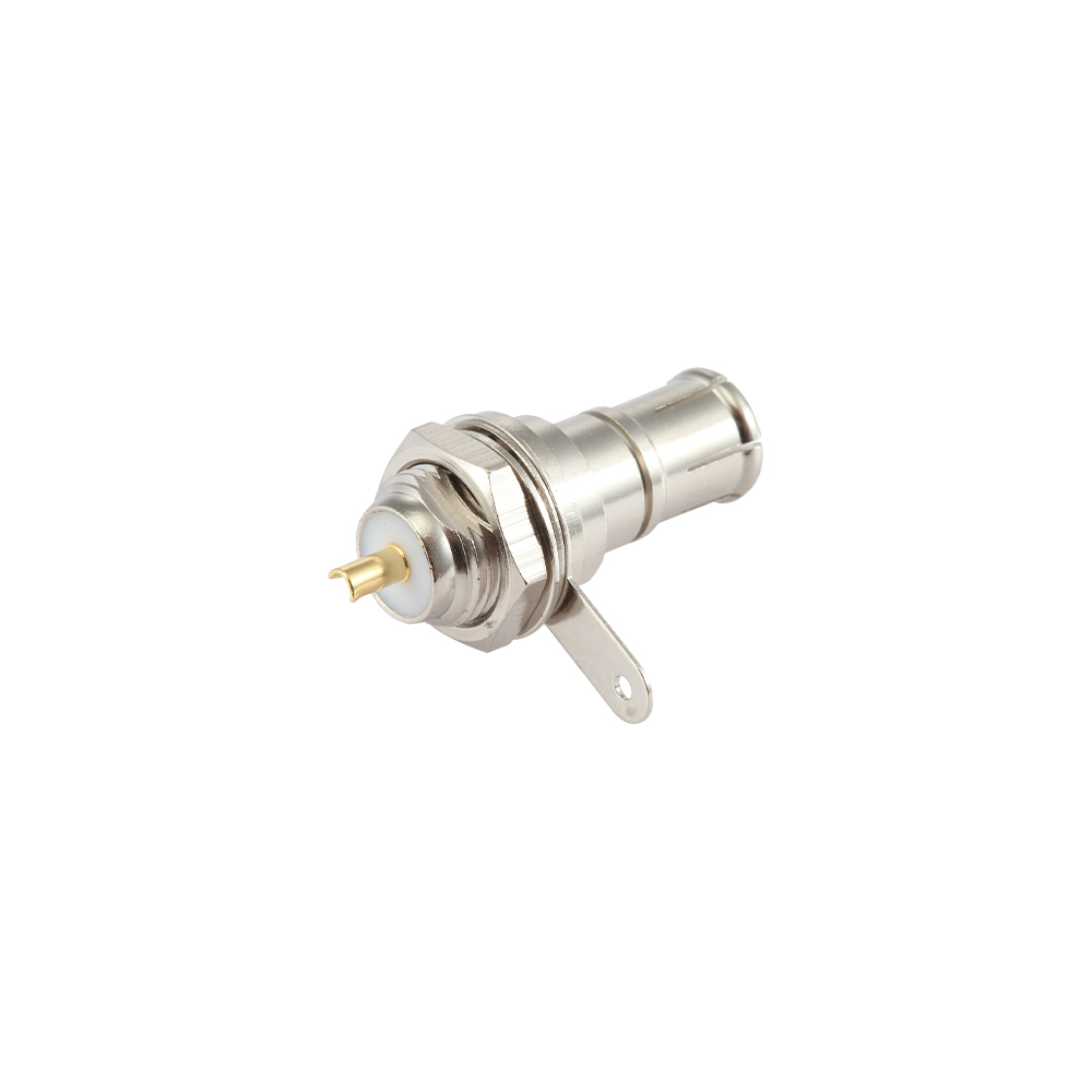
BNC Bulkhead Mount RF Coaxial ConnectorsBNC Bulkhead Mount RF Coaxial ConnectorsSingle-hole nut-mount BNC connectors for panel or chassis mounting, offering solder cup, PC tail, crimp, and clamp options with 50Ω and 75Ω versions for clean front-panel test points.View Product →

PCB connectors solder directly to a circuit board, with either vertical or right-angle orientation. They are common in RF modules, instrumentation front ends, and embedded video hardware where the connector must sit close to the active circuitry.
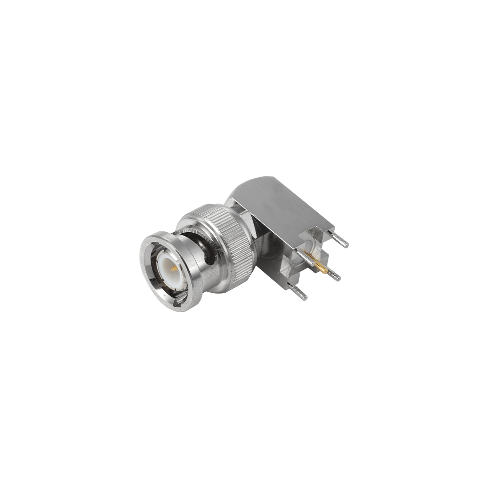
BNC PCB Mount RF Coaxial ConnectorsBNC PCB Mount RF Coaxial ConnectorsPCB-mount BNC connectors in through-hole or SMT styles with right-angle or vertical orientations, engineered to maintain impedance through the board transition for high-frequency signal integrity.View Product →

Other useful body styles include flange-mount connectors for rigid panel installation, protective caps for unused ports, and termination loads for calibration. If your system combines BNC with other interfaces, intertype adapters keep the impedance stable; for example, a BNC-to-SMA adapter lets a precision SMA test cable terminate in a BNC instrument port without soldering.

How to Choose the Right BNC Size for Your Application

The correct selection order is impedance first, cable second, mechanical form third. Working in any other order usually produces a connector that fits one part of the system but fails somewhere else.

  1. Determine the system impedance. Check the instrument label, cable markings, or system documentation. Mixing 50-ohm and 75-ohm BNCs is the single most common field error.
  2. Measure the cable outer diameter. Use a caliper or the cable datasheet. Select a BNC with a clamping range that matches that diameter and a center pin sized for the conductor.
  3. Select gender and body style. Confirm whether you need a plug or jack, and whether the connector will be cable-mounted, bulkhead-mounted, or PCB-mounted.
  4. Inspect the center pin and dielectric. A compliant 50-ohm pin should measure about 1.3 mm; a compliant 75-ohm pin about 1.0 mm. Check that the dielectric is clean and not recessed more than specified.
  5. Verify plating and environmental requirements. Nickel is standard for general use; gold is preferred for precision test applications where low and stable contact resistance matters.

Buying purely on price is risky in BNC parts. Low-cost connectors may use thinner gold plating, out-of-tolerance center pins, or dielectric materials that change impedance under temperature. Ask for a dimensional drawing or verify the pin diameter with a caliper before committing to a large order.

BNC Size FAQ

Can a 50-ohm BNC and a 75-ohm BNC be used together?

Physically yes, electrically no. The bayonet shells mate perfectly, but the impedance discontinuity at the junction causes a reflection. For video at low frequency the effect may go unnoticed; for RF measurement or communication signals it can degrade accuracy and increase attenuation. If you must test a 75-ohm device with a 50-ohm instrument, use a correctly rated impedance adapter rather than relying on the connector mismatch.

How can I tell a 50-ohm BNC from a 75-ohm BNC visually?

Look at the male center pin and the surrounding dielectric. A 50-ohm pin is thicker, about 1.3 mm, and the dielectric is recessed slightly behind the mating face. A 75-ohm pin is thinner, about 1.0 mm, and the dielectric sits almost flush with the face. Measuring the pin with a caliper gives the most reliable answer.

What cable diameters work with a BNC connector?

It depends on the connector’s rear barrel range. The most common flexible cables are RG-58 and RG-59 at roughly 5–6 mm outer diameter, RG-174 at 2.5 mm for compact jumpers, and RG-6 at about 6.9 mm for modern video runs. Always match the connector’s clamp range to the actual cable jacket, not just to a cable name printed on the spool.

Is a TNC connector the same size as a BNC?

The interface dimensions are similar in geometry, but not identical. TNC uses a threaded coupling nut and a slightly different shell profile, so it cannot be safely substituted for BNC. If your system experiences strong vibration, TNC is the better choice because its thread resists loosening. For standard bench and rack work, BNC remains the faster, more convenient bayonet option.

Related products
JC3.650.067 MCX-JWB2
VIEW MORE
JC3.650.068 MCX-JWB3
VIEW MORE
JC3.650.069 MCX-JB2
JC3.650.069 MCX-JB2
JC3.650.069 MCX-JB2
JC3.650.069 MCX-JB2
VIEW MORE
JC3.650.1844  MCX-JB2-3
JC3.650.1844 MCX-JB2-3
JC3.650.1844  MCX-JB2-3
JC3.650.1844 MCX-JB2-3
VIEW MORE
JC3.650.1854  MCX-JWB2-5
JC3.650.1854 MCX-JWB2-5
JC3.650.1854  MCX-JWB2-5
JC3.650.1854 MCX-JWB2-5
VIEW MORE
JC3.650.622  MCX-C-75J1.5
JC3.650.622 MCX-C-75J1.5
JC3.650.622  MCX-C-75J1.5
JC3.650.622 MCX-C-75J1.5
VIEW MORE
JC3.650.1301  MCX-C-75JW1.5
JC3.650.1301 MCX-C-75JW1.5
JC3.650.1301  MCX-C-75JW1.5
JC3.650.1301 MCX-C-75JW1.5
VIEW MORE
JC3.650.1307  MCX-C-75J1.5-1
JC3.650.1307 MCX-C-75J1.5-1
JC3.650.1307  MCX-C-75J1.5-1
JC3.650.1307 MCX-C-75J1.5-1
VIEW MORE
JC3.650.059  MCX-C-JW1.5
JC3.650.059 MCX-C-JW1.5
JC3.650.059  MCX-C-JW1.5
JC3.650.059 MCX-C-JW1.5
VIEW MORE
JC3.650.062 MCX-C-J1.5
VIEW MORE
JC3.650.066  MCX-C-J3
JC3.650.066 MCX-C-J3
JC3.650.066  MCX-C-J3
JC3.650.066 MCX-C-J3
VIEW MORE
JC3.650.076  MCX-C-JW1.5-4
JC3.650.076 MCX-C-JW1.5-4
JC3.650.076  MCX-C-JW1.5-4
JC3.650.076 MCX-C-JW1.5-4
VIEW MORE
News & Updates
75 Ohm vs 50 Ohm BNC Connector: Differences, Compatibility, and How to Choose
Industry News
2026-09-22
75 Ohm vs 50 Ohm BNC Connector: Differences, Compatibility, and How to Choose
A 50 ohm BNC connector is built for 50 ohm systems, and a 75 ohm BNC connector is built for 75 ohm systems. The two always fit each other mechanically — same bayonet shell, same coupling lugs, same pin arrangement — but they are not electrically equivalent: the characteristic impedance each connector maintains is different, and the intended applications are different. Choose 50 ohm for RF, telecom, and test equipment; choose 75 ohm for video, broadcast, and surveillance links. 50 Ω BNCRF, radio, telecom, GPS, and test instrumentation; solid PTFE dielectric; exposed center pin; matches RG-58 or RG-213. 75 Ω BNCComposite video, SDI, CCTV, and CATV; air-spaced or webbed dielectric; recessed touch-proof center pin; matches RG-59 or RG-6. Mixing themMechanically compatible, electrically mismatched; about 14 dB return loss at the junction; avoid in precise RF and digital video paths. At baseband video frequencies, a mismatched BNC junction may only produce a faint ghost. On an RF transmitter or an HD-SDI link, the same junction raises VSWR and closes the eye pattern. This article compares the two connector types, shows what happens when they meet, and explains how to choose the right part. What the Impedance Number Means The number on a BNC connector is the characteristic impedance of the transmission-line path it maintains. A connector of the wrong impedance acts as a small discontinuity: part of the signal passes through, and part reflects back toward the source. Characteristic impedance is the ratio of the voltage wave to the current wave traveling down a uniform line. It is set by the ratio of the outer conductor diameter to the inner conductor diameter and by the dielectric between them. Cable length does not change it, and neither does the position of a switch. Why 50 Ω became the RF standard Fifty ohms is a compromise. The theoretical optimum impedance for maximum power handling is near 30 ohms, and the optimum for minimum attenuation is near 77 ohms. A 50 ohm system gives up a little on both curves and keeps the best overall balance, which is why it dominates radio, cellular infrastructure, GPS, Wi-Fi backhaul, and RF test equipment. Why 75 Ω became the video standard Seventy-five ohms sits close to the minimum-attenuation point, so it delivers the longest cable run before amplification is needed. That property made it the natural choice for analog video, broadcast, CCTV, and cable television, and the convention carried over to digital video and SDI. A 50 ohm BNC connector is rated to roughly 4 GHz in typical RF use, while 75 ohm BNC parts are almost always used well below 1 GHz, where the BNC shell size still behaves cleanly. Construction Differences Between 50 Ω and 75 Ω BNC Connectors Externally the two BNC types look identical and share the same shell, bayonet, and mating dimensions. The differences are inside: the dielectric geometry and the center contact. A coaxial connector has to preserve the conductor ratio and the dielectric environment of the cable it terminates. Because the BNC shell is standardized, the center contact and the insulator carry the impedance. A 50 Ω BNC plug uses solid PTFE insulation, and its center pin protrudes beyond the dielectric face so it can be gripped. A 75 Ω BNC plug uses a modified dielectric profile — often air-spaced or webbed — and its center pin is recessed below the dielectric nose, which makes the part touch-proof. This recessed pin is a deliberate design of the 75 Ω BNC standard, not a manufacturing accident. Table 1. The two BNC impedance versions differ in dielectric, center contact, intended cable, and application. Characteristic 50 Ω BNC 75 Ω BNC Impedance 50 ohms 75 ohms Reference standard MIL-STD-348, IEC 60169-8 IEC 60169-12, EN 122190 Dielectric Solid PTFE Air-spaced or webbed dielectric Center contact Protruding, touchable Recessed, touch-proof Typical cable RG-58, RG-213 RG-59, RG-6 Typical application RF, telecom, test, GPS Video, SDI, CCTV, CATV When you assemble a cable, match the connector impedance to the cable impedance before you match the connector to the cable diameter. A 50 Ω BNC designed for flexible cable, crimped onto RG-58, is the standard RF jumper; a 75 Ω BNC crimped onto RG-59 is the video equivalent. BNC Connectors for Flexible Coaxial Cables with Matched ImpedanceThis connector family terminates RG-58, RG-59, and similar flexible cables with controlled center-pin geometry, helping maintain the intended 50 or 75 ohm impedance through the junction and minimize reflections in the assembled cable.View Product → Can You Mix 50 Ω and 75 Ω BNC Connectors? You can — the bayonet locks firmly — but the result is a small impedance step that reflects part of the signal. If a 75 Ω video path contains a 50 Ω connector, the reflection coefficient at the junction is (50 − 75) ÷ (50 + 75) = −0.20: about 20 percent of the voltage wave sees a discontinuity. The VSWR is 1.50:1, the return loss is close to 14 dB, and about 4 percent of the power bounces back. Table 2. The mismatch penalty of inserting a 50 Ω BNC into a 75 Ω line; the same numbers apply in the reverse direction. Metric Value for a 50 Ω connector on a 75 Ω path Reflection coefficient 0.20 VSWR 1.50:1 Return loss About 14 dB Reflected power 4 percent Whether those numbers matter depends on frequency and bit rate. At baseband video up to a few megahertz, the wavelength is tens of meters, so a centimeter-sized connector mismatch may be invisible or show up as a faint echo. On an HD-SDI link at 1.485 Gbit/s and beyond, the same junction costs data margin and can cause picture dropouts or loss of lock. In an RF test setup, any wrong-impedance adapter, barrel, or connector corrupts calibration; in a transmitter chain, the reflected power changes what the output stage sees and can trip protective circuits. Instrumentation and test boards should keep the impedance reference intact from the board to the cable. A PCB-mount 50 Ω BNC with a short, well-shaped ground transition preserves that reference at the point where the signal enters or leaves the board. PCB-Mount BNC Connectors for Board-Level Signal IntegrityDirect board-mount BNCs preserve the impedance reference at the PCB transition, making them suitable for test boards and instrumentation where a short, controlled launch into the circuit is needed.View Product → How to Identify a 50 Ω or 75 Ω BNC Connector The fastest check is visual: look at the mating face of a plug. A protruding center pin surrounded by solid PTFE means 50 Ω. A recessed center pin hidden below a dielectric nose means 75 Ω. Plug face: pin exposed = 50 Ω; pin recessed and touch-proof = 75 Ω. Body and boot markings: many parts are stamped “50 Ω”, “75 Ω”, or with a specific series; a plain “BNC” marking does not prove the impedance. Cable jacket: RG-58 and RG-213 are 50 Ω; RG-59 and RG-6 are 75 Ω — but check the marking on the cable, because connectors can be fitted onto the wrong cable. Measurement: a time-domain reflectometer or a network analyzer gives a definitive value when the application cannot tolerate doubt. Adapters: a BNC within-type adapter couples two connectors mechanically; it does not convert impedance. Using one only moves the junction. Treat parts stamped “50/75 Ω” with suspicion. Some utility connectors carry both ratings because they are intended for low-frequency control or video links with loose requirements. In a broadcast or precision RF system, that kind of part is not a substitute for a true 50 Ω or true 75 Ω component. How to Choose the Right BNC Connector Impedance Decide the system impedance first, then select the cable, the connector termination, and the mounting style to match. The impedance must be consistent from the equipment port to the far end of the cable. Identify the system impedance from the equipment datasheet or port label. RF instruments, radios, GPS receivers, and most antennas are 50 Ω. Cameras, video routers, monitors, and SDI gear are 75 Ω. Select cable of the same impedance. Use RG-58 or RG-213 for 50 Ω; RG-59 or RG-6 for 75 Ω. Match the termination to the cable. Crimp connectors suit volume production, clamp and solder types suit field repair; never force a connector body designed for one cable diameter onto another. Choose the mounting style. Flexible-cable connectors make jumpers, bulkhead connectors terminate panels and chassis, PCB connectors land on circuit boards, and flange connectors bolt to a flat surface. Check the VSWR or return-loss specification if the frequency is high or the run is long. For 50 Ω RF work, a 1.30:1 VSWR at the operating frequency is a reasonable target; for video, the connector should state 75 Ω with an explicit frequency limit. If you are deciding between BNC and other families, the RF coaxial connector selection guide explains how BNC compares with TNC, N, SMA, and related series, and which electrical parameters matter most. Where a cable enters a chassis, use a bulkhead-mount connector so the shield bonds directly to the panel and the cable is mechanically relieved. That keeps the impedance transition short and prevents strain on the solder or crimp point. Bulkhead-Mount BNC Connectors for Chassis and Panel FeedthroughSingle-hole panel-mount BNCs bond the shield directly to the chassis, providing mechanical strain relief and a compact feedthrough that keeps the impedance path short when routing cables through enclosure walls.View Product → Frequently Asked Questions Is a 50 Ω BNC physically compatible with a 75 Ω BNC? Yes. The shell diameter, bayonet lugs, and center-pin diameter are the same, so a 50 Ω plug locks firmly into a 75 Ω jack and vice versa. The compatibility is mechanical only; the electrical impedance still differs. Can mixing 50 Ω and 75 Ω BNC connectors damage equipment? Not directly. The junction reflects a few percent of the signal power, which is usually absorbed by the cable and the connectors. The practical risks are reduced video margin, RF calibration errors, and transmitter VSWR protection tripping on high-power links. How can I tell whether my cable is 50 Ω or 75 Ω? Read the jacket marking if it is legible: RG-58 and RG-213 are 50 Ω; RG-59 and RG-6 are 75 Ω. When the marking is missing, verify the connector geometry or measure the line if the application needs an impedance budget. Why is the 75 Ω BNC center pin recessed? The recessed, touch-proof center contact is part of the 75 Ω BNC design. It prevents the user from touching a live pin while patching broadcast or video racks, and it reduces the chance of an accidental short to the shell. Do I need 75 Ω BNC connectors for SDI video? Yes. SDI is a 75 Ω standard end to end. A 50 Ω connector inserted anywhere in the path adds a reflection at the serial data rate; short test patches may pass, but production links should remain all 75 Ω. .article-section table{display:table!important;width:100%;border-collapse:collapse;margin:0 0 18px;} .article-section thead{display:table-header-group!important;} .article-section tbody{display:table-row-group!important;} .article-section tr{display:table-row!important;} .article-section th{display:table-cell!important;font-weight:bold;border:1px solid #cccccc;padding:8px;} .article-section td{display:table-cell!important;border:1px solid #cccccc;padding:8px;} .article-section caption{caption-side:bottom;font-size:16px;margin-bottom:12px;font-style:italic;color:#808080;} .article-section ol{margin-bottom:12px;list-style-type:decimal;list-style-position:inside;padding-left:0;} .article-section ul{margin-bottom:12px;list-style-type:disc;list-style-position:inside;} .article-section li{list-style:inherit;font-size:16px;margin-bottom:6px;} .article-section h2{font-size:1.55em;font-weight:bold;text-align:left;margin-top:40px;margin-bottom:10px;border-left:5px solid #0077cc;padding-left:14px;color:#0a2a4a;} .article-section h3{font-size:1.2em;font-weight:bold;text-align:left;margin-top:28px;margin-bottom:8px;color:#0a2a4a;} .article-section p{font-size:16px!important;margin-bottom:12px;} .article-section .comparison-grid{display:grid;grid-template-columns:repeat(auto-fit,minmax(180px,1fr));gap:14px;margin:16px 0 20px;} .article-section .comparison-card{background:#f5f7fa;border:1px solid #e2e6ec;border-radius:8px;padding:14px 16px;} .product-card{display:block;margin:20px 0;border:1px solid #e5e7eb;border-radius:10px;overflow:hidden;font-style:normal;background:#fff} .pc-inner{display:flex;text-decoration:none;color:inherit;align-items:center;min-height:120px} .pc-img{width:160px;min-width:160px;aspect-ratio:4/3;height:auto;min-height:120px;object-fit:cover;flex-shrink:0;display:block;align-self:stretch} .pc-body{padding:12px 16px;flex:1;min-width:0;display:flex;flex-direction:column;align-self:stretch;justify-content:center} .pc-title{display:block;font-size:15px;font-weight:600;color:#111;margin:0 0 6px;line-height:1.4} .pc-desc{display:-webkit-box;font-size:13px;color:#6b7280;margin:0 0 8px;line-height:1.5;overflow:hidden;-webkit-line-clamp:2;line-clamp:2;-webkit-box-orient:vertical} .pc-cta{display:block;font-size:13px;font-weight:600;color:inherit;margin-top:auto} .pc-inner:hover .pc-title{text-decoration:underline} .article-section a:not(.pc-inner),article a:not(.pc-inner){color:inherit}.pc-cta{color:inherit!important}...
50 Ohm Coax Cable Explained: What It Means, Why It Matters, and How to Choose
Industry News
2026-09-11
50 Ohm Coax Cable Explained: What It Means, Why It Matters, and How to Choose
A 50 ohm coax cable is a transmission line with a characteristic impedance of 50 ohms, and it is the default choice in most RF systems because it balances low signal loss with reasonable power-handling capability. The “50 ohm” rating does not refer to a DC resistance you can measure with a multimeter; it describes how voltage and current travel along the cable at radio frequencies. This article explains what 50 ohm impedance really means, why the industry adopted it, how it compares with other impedances, and what to check before you buy. If you need a full step-by-step selection method, see our RF coaxial connector guide. What Does 50 Ohm Mean in a Coax Cable? The characteristic impedance of a cable is the ratio of voltage to current in a wave traveling along it, and it is fixed by the cable’s geometry and dielectric material. For a coaxial cable, the impedance is approximately Z0 = (138 / sqrt(εr)) × log10(D/d), where D is the inner diameter of the outer shield, d is the outer diameter of the inner conductor, and εr is the relative permittivity of the dielectric. This impedance is independent of cable length. A 10 m and a 100 m length of the same 50 ohm cable will both show roughly the same characteristic impedance when measured with a network analyzer. A DC ohmmeter will only read a low series resistance, often near 0 ohm for a short piece or several ohms for a long run, so it cannot be used to verify a 50 ohm rating. Characteristic impedance is set by construction, not by length. The impedance value is meaningful only at frequencies where the signal wavelength is comparable to or smaller than the cable length. A mismatch creates reflections, which increase insertion loss and signal distortion. Why 50 Ohm Became the RF Standard The 50 ohm standard emerged because it was the best practical compromise between low attenuation and high power handling for air-dielectric cables. For a coaxial line with air dielectric, the maximum power-handling peak is near 30 ohm and the minimum attenuation is near 77 ohm. The geometric mean of those two values is approximately 48 ohm, which rounded naturally to the 50 ohm we use today. When solid polyethylene and other low-loss dielectrics became standard, the optimum values shifted slightly, but 50 ohm remained close enough and was already widely used by telecommunications and test-equipment engineers. Radar, radio transceivers, laboratory instruments, and later cellular and wireless equipment all standardized on 50 ohm. 50 Ohm vs 75 Ohm vs Other Impedances For general-purpose RF work, choose a 50 ohm cable; choose a 75 ohm cable only for low-loss receiving applications such as broadcast video or television, where power handling is less critical. The table compares the main differences. Comparison of common coaxial cable impedances in RF and video systems. Values are typical; always check the cable datasheet. Impedance Typical use Signal loss Power handling Connector types 50 ohm Wireless, test equipment, radio, antenna feeders, IoT Low Moderate to high BNC, N, SMA, TNC, UHF 75 ohm Broadcast video, CCTV, cable TV, telephony Lower than 50 ohm for the same outer size Lower BNC, F, RCA 93 ohm Legacy data transmission, early LANs Very low for certain low-speed data Very low BNC (rare) Using a 75 ohm cable in a 50 ohm system creates a mismatch that reflects part of the signal. At low frequencies and short lengths the effect may be negligible, but above a few hundred megahertz or for long cable runs the added ripple and loss usually make it unacceptable. How to Choose a 50 Ohm Coax Cable Start by setting the maximum acceptable loss at your operating frequency, then verify power handling, mechanical flexibility, shielding, and impedance tolerance. The most common mistake is buying the cheapest RG-58 lookalike without checking attenuation at the actual frequency of interest. Determine the highest frequency you will transmit. Loss rises with frequency, so a cable that works at 100 MHz may be unusable at 6 GHz. Calculate total loss from the cable’s attenuation per metre, often specified in dB per 100 m at 1 GHz; multiply by your run length and add connector loss. Check the outer conductor construction. Braid is flexible but leaks; foil plus braid gives better shielding; semi-rigid and corrugated copper give the lowest loss and best shielding for fixed installations. Check impedance tolerance. A good 50 ohm flexible cable typically holds characteristic impedance within ±2 ohm; poor-quality cables can drift more and cause higher VSWR. Verify the connector family and mating interface. A 50 ohm SMA connector is not the same as a 50 ohm N connector mechanically or electrically, and neither should be forced onto a 75 ohm BNC port. Common generic 50 ohm cable families include RG-58/U for short flexible patch leads, RG-213/U for higher-power base-station runs, and low-loss foam-dielectric cables for long feeders. The actual performance depends on the construction quality, so always compare datasheet attenuation curves before ordering. Matching Connectors to a 50 Ohm Cable Every 50 ohm cable needs a 50 ohm connector that matches the cable diameter and the target port; mismatching connector impedances creates reflections and can damage the interface. For example, a 75 ohm BNC connector can mate with a 50 ohm BNC connector, but the impedance step at the junction increases VSWR and the centre pins are not always dimensionally compatible. N-type and SMA connectors are far more consistent in 50 ohm systems, while TNC provides a threaded, weather-resistant version of BNC. SMA Connectors SMA is the first choice for frequencies up to 18 GHz and for compact modules such as radios, antennas, and test fixtures. Choose an SMA connector that matches your cable type, whether flexible, semi-rigid, or microstrip. SMA RF Coaxial Connectors for Broadband ApplicationsExplore SMA connectors with 50 ohm impedance, supporting DC to 18 GHz on semi-rigid cable. They suit compact modules and high-frequency circuits mentioned in the preceding text.View Product → N Connectors N connectors are rugged, 50 ohm connectors with outstanding repeatability from DC to 11 GHz or higher. They are common on base-station filters, RF amplifiers, and outdoor antenna feeders. N RF Coaxial Connectors with Screw CouplingThese rugged 50 ohm connectors operate up to 11 GHz on semi-rigid cable. Ideal for base-station filters and outdoor feeders, as noted in the surrounding discussion.View Product → BNC Connectors BNC connectors are convenient for quick connections, but verify that the specific BNC is rated for 50 ohm and for your frequency range. The same shell is also used for 75 ohm video circuits, so check the datasheet before mating. BNC RF Coaxial Connectors with Bayonet CouplingCheck these 50 or 75 ohm BNC connectors for quick connect-disconnect needs. The context warns to verify frequency and impedance ratings before mating, making this page useful.View Product → When you assemble a cable, confirm that the connector is specified for the exact cable family you are using, such as flexible braided cable or semi-rigid cable. If the two port interfaces are different, use a low-loss 50 ohm RF adapter rather than adapting with a long cable. Typical Applications and Installation Checks You will find 50 ohm coax cable in wireless infrastructure, test and measurement, avionics, IoT devices, and any system where a transceiver drives an antenna. In these applications, the cable impedance is part of a matched chain from the connector on the PCB to the antenna feed point. Bench test leads and spectrum-analyzer connections use short 50 ohm patch cables. Base-station antenna feeders use low-loss 50 ohm cable with N-type connectors. Software-defined radios often route RF into a 50 ohm SMA female port. GPS receivers, telematics, and radio modules share the same 50 ohm impedance convention. For outdoor installations, check whether the cable has a weather-resistant jacket, and add a surge protector or lightning protection component near the entry point. A protector designed for 50 ohm operation will maintain the system’s characteristic impedance through the surge path. Frequently Asked Questions These are the questions engineers most often ask before selecting a 50 ohm cable. Can I use a 75 ohm cable in a 50 ohm system? Yes, but only for a short temporary test and not at high power or high frequency. The impedance mismatch creates a reflection coefficient of about (75-50)/(75+50), or 0.2, which means roughly 4% of the signal power is reflected. Return loss is only about 14 dB, which may be acceptable for bench work but is rarely acceptable for a transmitter. Does a 50 ohm cable measure 50 ohm on a multimeter? No. A multimeter applies DC and measures the series resistance of the centre conductor and shield, which is usually below 10 ohm for a short cable. Characteristic impedance is an AC wave property and can only be measured correctly with impedance analysis at RF, for example with a network analyzer. What is the difference between 50 ohm and 75 ohm BNC connectors? The basic shell is the same, but 75 ohm BNC connectors have a different centre-conductor profile and are not interchangeable with 50 ohm types without degrading the interface. A 50 ohm plug will physically mate with a 75 ohm jack, but the impedance change and poor contact force can increase VSWR and damage the jack over repeated connections. What cable should I buy for a 50 ohm antenna feeder? Choose the thinnest cable that passes your loss budget. For short indoor runs, RG-58 type is convenient. For long outdoor runs or frequencies above 1 GHz, choose a low-loss 50 ohm cable with a closed-cell jacket and N-type connectors, and verify its attenuation at your actual frequency. .article-section table{display: table!important;} .article-section thead{display: table-header-group!important;} .article-section tbody{display: table-row-group!important;} .article-section tr{display: table-row!important;} .article-section th{display: table-cell!important;} .article-section td{display: table-cell!important;} .article-section caption{caption-side:bottom;font-size:16px;margin-bottom:12px;font-style:italic;color:#808080;} .article-section th{font-weight:bold;border:1px solid #cccccc;padding:8px;} .article-section td{border:1px solid #cccccc;padding:8px;} .article-section ol{margin-bottom:12px;list-style-type:decimal;list-style-position:inside;padding-left:0;} .article-section ul{margin-bottom:12px;list-style-type:disc;list-style-position:inside;} .article-section li{list-style:inherit;font-size:16px;margin-bottom:6px;} .article-section h2{font-size:1.55em;font-weight:bold;text-align:left;margin-top:40px;margin-bottom:12px!important;border-left:5px solid #0077cc;padding-left:14px;color:#0a2a4a;} .article-section h3{font-size:1.2em;font-weight:bold;text-align:left;margin-top:28px;margin-bottom:12px;color:#0a2a4a;} .article-section p{font-size:16px!important;margin-bottom:12px;} .product-card{display:block;margin:20px 0;border:1px solid #e5e7eb;border-radius:10px;overflow:hidden;font-style:normal;background:#fff} .pc-inner{display:flex;text-decoration:none;color:inherit;align-items:center;min-height:120px} .pc-img{width:160px;min-width:160px;aspect-ratio:4/3;height:auto;min-height:120px;object-fit:cover;flex-shrink:0;display:block;align-self:stretch} .pc-body{padding:12px 16px;flex:1;min-width:0;display:flex;flex-direction:column;align-self:stretch;justify-content:center} .pc-title{display:block;font-size:15px;font-weight:600;color:#111;margin:0 0 6px;line-height:1.4} .pc-desc{display:-webkit-box;font-size:13px;color:#6b7280;margin:0 0 8px;line-height:1.5;overflow:hidden;-webkit-line-clamp:2;line-clamp:2;-webkit-box-orient:vertical} .pc-cta{display:block;font-size:13px;font-weight:600;color:inherit;margin-top:auto} .pc-inner:hover .pc-title{text-decoration:underline} .article-section a:not(.pc-inner),article a:not(.pc-inner){color:inherit}.pc-cta{color:inherit!important}...
Coax Cable Comparison: RG58 vs RG59 vs RG6 vs RG11 and Connector Matching
Industry News
2026-08-14
Coax Cable Comparison: RG58 vs RG59 vs RG6 vs RG11 and Connector Matching
Choosing a coaxial cable without comparing impedance, attenuation, and connector compatibility usually ends in poor signal quality. The practical rule is short: 50 Ω cables such as RG58 are for radio equipment, test instruments, and compact RF modules, while 75 Ω cables such as RG59, RG6, and RG11 are for video, TV, satellite, and broadband. Inside each impedance family, the decision comes down to run length, operating frequency, and how easily the cable must bend and terminate. This coax cable comparison covers the four most common RG cables, explains the numbers that matter, and maps each cable to the connector series that will actually fit it. What a Coax Cable Comparison Must Cover Six parameters determine whether a cable will work in your application: characteristic impedance, attenuation per unit length, frequency ceiling, outer diameter, flexibility, and shielding quality. Of these, impedance and attenuation cause the most mis-buys. Characteristic impedance — 50 Ω is the standard for RF systems, test equipment, and antennas; 75 Ω is the standard for video, TV, and broadband. Mismatches create reflections and extra loss. Attenuation — Measured in dB per 100 feet or per metre, attenuation climbs as frequency rises. A cable that works at 10 MHz can be unusable at 2.4 GHz over the same distance. Frequency ceiling — The highest usable frequency before loss or dimensional instability makes the cable impractical. Outer diameter and flexibility — Thick cables such as RG11 have low loss but a large bend radius; thin cables such as RG58 route easily but lose more signal. Shielding — Braid and foil layers reject interference; double-shielded constructions suit noisy industrial environments. Cable-to-connector fit — The connector series must match the cable's impedance and accept its outer conductor and dielectric diameters. RG58 vs RG59 vs RG6 vs RG11: Side-by-Side Once impedance splits the group into 50 Ω and 75 Ω families, the remaining differences are mainly attenuation, diameter, and stiffness. The table below condenses the comparison. Table 1 — Typical parameters for common RG coaxial cables. Attenuation values are per 100 ft at 100 MHz and vary with manufacturer and construction. Parameter RG58 RG59 RG6 RG11 Characteristic impedance 50 Ω 75 Ω 75 Ω 75 Ω Outer diameter 4.95 mm 6.15 mm 6.9-7.0 mm 10.3 mm Dielectric Solid PE Solid PE Foam PE Foam PE Typical attenuation at 100 MHz ~4.5 dB/100 ft ~3.5 dB/100 ft ~2.0 dB/100 ft ~1.5 dB/100 ft Common applications Test leads, short RF interconnects Analog video, CCTV Satellite, TV, broadband Long outdoor drops RG58: Best for Short 50 Ω Interconnects RG58 is the right choice for short 50 Ω interconnects when flexibility and easy termination matter more than ultra-low loss. Its slim 4.95 mm diameter and soldered or crimped centre conductor make it the default cable for test leads, radio patch cords, and GPS pigtails. Typical loss runs about 4.5 dB per 100 ft at 100 MHz, so keep runs under roughly 10 m (33 ft) for UHF and shorter still at 1 GHz. RG59: Acceptable for Short 75 Ω Analog Video RG59 works acceptably for short 75 Ω analog video runs, but becomes too lossy above roughly 50 MHz or beyond 30-50 m (100-165 ft). It is slightly thicker than RG58 and easier to terminate with BNC connectors than RG6. However, attenuation of about 3.5 dB per 100 ft at 100 MHz makes it a poor choice for high-definition video or long camera drops. RG6: The Default 75 Ω Broadband Cable RG6 is the default 75 Ω cable for satellite, cable TV, and residential broadband because it combines lower attenuation with stronger shielding. Foam polyethylene dielectric reduces loss to roughly 2.0 dB per 100 ft at 100 MHz, more than 40 percent lower than RG59. Quad-shielded versions reject interference in congested environments, and F-type connectors are the standard termination. RG11: Low Loss for Long Outdoor Drops RG11 is the low-loss 75 Ω option for long outdoor drops where RG6 attenuation would force an amplifier. Its thicker foam dielectric and larger conductor cut loss to about 1.5 dB per 100 ft at 100 MHz, extending usable runs to several hundred feet. The trade-off is a stiff 10.3 mm cable with a large bend radius and demanding termination, so reserve RG11 for trunk lines and multi-dwelling distribution. Frequency and Distance: How Far Can Each Cable Really Run? Attenuation, not signalling speed, is what limits real coax runs. The following guidance works for most installations, assuming connectors are correctly installed and the system is impedance-matched. Below 30 MHz (HF radio): RG58 can cover 30 m (100 ft) with acceptable loss; beyond that, move to a lower-loss 50 Ω feeder such as RG213 or RG8-class cable. 50 to 500 MHz (VHF/UHF, TV): on the 75 Ω side, use RG6; RG59 is only for short analog drops. On the 50 Ω side, keep RG58 under 10 m and switch to a foam-dielectric cable for longer runs. Above 1 GHz: RG58 and RG59 become impractical beyond a few metres. Use low-loss foam-dielectric, semi-rigid, or flexible microwave cables, and pair them with SMA or N connectors. Which Connector Goes With Which Cable Pick the connector after the cable, not before. The connector must match the cable's impedance and accept its outer diameter; forcing the wrong fit is a common cause of intermittent VSWR and signal drop. Table 2 — Matching coaxial cable families to connector interfaces and typical applications. Cable Impedance Typical connector series Common applications RG58 50 Ω BNC, SMA, TNC, N Test leads, radio interconnects, GPS RG59 75 Ω BNC, F-type CCTV, composite video RG6 75 Ω F-type, BNC Satellite, cable TV, broadband RG11 75 Ω F-type Long broadband distribution RG213 / RG8-class 50 Ω N, UHF Base stations, high-power feeders BNC and TNC for Thin Cables BNC is the standard connector for RG58 and RG59 in test and video applications, while TNC adds a threaded coupling that resists vibration. BNC's bayonet lock is fast and reliable for patch cords and instrument front panels. For RG58 patch cords and RG59 video drops, a complete range of BNC connectors for flexible coaxial cable covers straight, right-angle, and bulkhead styles. Custom BNC Connectors for Flexible Cable Manufacturer, SupplierYangzhou Jingcheng Electronics Co., Ltd. is China BNC Connectors for Flexible Cable manufacturer and BNC Connectors for Flexible Cable su...View Product → N-Type for Outdoor and Higher-Power Runs N-type is the 50 Ω outdoor workhorse, sealed against moisture and consistent up to 11 GHz, making it the safest choice for exposed radio feeders. N connectors handle higher power than BNC and SMA, and their weatherproof construction suits antennas and base stations. When coax runs leave the building, choose N-type connectors for flexible coaxial cable with crimp or clamp attachment. Custom N Connectors for Flexible Cable Manufacturer, SupplierYangzhou Jingcheng Electronics Co., Ltd. is China N Connectors for Flexible Cable manufacturer and N Connectors for Flexible Cable suppli...View Product → SMA for Compact Modules SMA is the compact 50 Ω connector for small-diameter flexible and semi-rigid cables where board space is limited and frequency is high. SMA connectors are rated well into the microwave range and appear on radio modules, attenuators, and test adapters. For small flexible cables, SMA connectors for flexible coaxial cable preserve the 50 Ω interface without the bulk of N or BNC. Custom SMA Connectors for Flexible Cable Manufacturer, SupplierYangzhou Jingcheng Electronics Co., Ltd. is China SMA Connectors for Flexible Cable manufacturer and SMA Connectors for Flexible Cable su...View Product → F-Type for RG6 and RG11 F-type is the inexpensive 75 Ω screw-on connector for RG6 and RG11, but quality depends heavily on the crimp tool and the connector finish. Use compression-style fittings with RG6 and RG11 and avoid cheap die-cast bodies that corrode outdoors. Application-Based Coax Recommendation Most coax selections fall into four application classes: radio, video, broadband, and test. Define the class first, then apply the cable and connector mapping above. HF/VHF/UHF radio (50 Ω): RG58 for short patch and jumper runs; RG213 or RG8-class for longer feeds; N or UHF connectors; ground and protect any outdoor run. CCTV and analog video (75 Ω): RG59 up to roughly 30-50 m; RG6 for longer runs; BNC connectors. Satellite, cable TV, and broadband (75 Ω): RG6 as the standard drop; RG11 for long outdoor spans; F-type connectors. Test and measurement (50 Ω): RG58 with SMA or BNC; verify VSWR and keep all adapters matched. Base stations and high-power transmitters (50 Ω): low-loss feeders with N or 7/16 DIN connectors; RG213-class cable or better. For any cable that crosses a roof or mast, add surge protection at the building entry point — see our coaxial lightning protection guide for rated product families and installation practice. When you need to narrow down an interface family from the many available series, our RF coaxial connector selection guide walks through each type and its intended use. Procurement Considerations Connector and cable defects rarely appear in an ohmmeter test; they show up as intermittent VSWR, corrosion, or noisy video after installation. Four checks catch most problems before purchase. Cable diameter versus connector entry: verify outer diameter and dielectric diameter against the connector drawing; a 0.2 mm difference can ruin a crimp. Plating: gold-plated contacts suit critical and low-intermodulation paths; nickel is acceptable for general indoor use. Impedance consistency: confirm 50 Ω or 75 Ω marking on both cable and connector; mixing families is the most common field error. Batch data: ask for attenuation and VSWR test values rather than relying only on catalogue figures. Single-source supply: buying cable, connectors, adapters, and surge protectors from one RF supplier keeps tolerances aligned; the detailed overview of our one-stop RF supply capability explains how that workflow is organised. Frequently Asked Questions These are the questions buyers ask most often when comparing coax cables. Is RG6 better than RG59? Yes for satellite, broadband, and any run over a few metres: RG6 has roughly 40 percent lower attenuation and stronger shielding. RG59 is only preferable for short indoor analog video runs where its flexibility and cheaper termination matter. Can I use RG58 for CCTV? No. CCTV cameras and recorders expect a 75 Ω signal path, while RG58 is 50 Ω. Use RG59 for short camera runs or RG6 for longer ones, terminated with BNC connectors. What happens if I mix 50 Ω and 75 Ω components? The impedance mismatch causes reflections that reduce signal level and increase return loss. The system may still work at low frequencies or short distances, but it becomes unreliable at UHF and above. Which connector should I use for RG58? BNC for general test and patch use, SMA for compact modules, TNC when vibration is a concern, and N for outdoor or higher-power runs. Start with impedance, then run length and frequency, then the connector family. That sequence turns any coax cable comparison into a short specification sheet — and it ensures the cable you choose can actually be terminated with connectors that are available, verified, and priced for your volume. .article-section table{display: table!important;} .article-section thead{display: table-header-group!important;} .article-section tbody{display: table-row-group!important;} .article-section tr{display: table-row!important;} .article-section th{display: table-cell!important;} .article-section td{display: table-cell!important;} .article-section table caption{caption-side:bottom;font-size:16px;margin-bottom:12px;font-style:italic;color:#808080;} .article-section th{font-weight:bold;border:1px solid #cccccc;padding:8px;} .article-section td{border:1px solid #cccccc;padding:8px;} .article-section ol{margin-bottom:12px;list-style-type:decimal;list-style-position:inside;padding-left:0;} .article-section ul{margin-bottom:12px;list-style-type:disc;list-style-position:inside;} .article-section li{list-style:inherit;font-size:16px;margin-bottom:6px;} .article-section h2{font-size:1.55em;font-weight:bold;text-align:left;margin-top:40px;margin-bottom:10px;border-left:5px solid #0077cc;padding-left:14px;color:#0a2a4a;} .article-section h3{font-size:1.2em;font-weight:bold;text-align:left;margin-top:28px;margin-bottom:8px;color:#0a2a4a;} .article-section p{font-size:16px!important;margin-bottom:12px;} .product-card{display:block;margin:20px 0;border:1px solid #e5e7eb;border-radius:10px;overflow:hidden;font-style:normal;background:#fff} .pc-inner{display:flex;text-decoration:none;color:inherit;align-items:center;min-height:120px} .pc-img{width:160px;min-width:160px;aspect-ratio:4/3;height:auto;min-height:120px;object-fit:cover;flex-shrink:0;display:block;align-self:stretch} .pc-body{padding:12px 16px;flex:1;min-width:0;display:flex;flex-direction:column;align-self:stretch;justify-content:center} .pc-title{display:block;font-size:15px;font-weight:600;color:#111;margin:0 0 6px;line-height:1.4} .pc-desc{display:-webkit-box;font-size:13px;color:#6b7280;margin:0 0 8px;line-height:1.5;overflow:hidden;-webkit-line-clamp:2;line-clamp:2;-webkit-box-orient:vertical} .pc-cta{display:block;font-size:13px;font-weight:600;color:inherit;margin-top:auto} .pc-inner:hover .pc-title{text-decoration:underline} .article-section a:not(.pc-inner),article a:not(.pc-inner){color:inherit}.pc-cta{color:inherit!important}...
Antenna Connector Types: SMA vs N Type vs TNC vs BNC vs RP-SMA Complete Guide
Industry News
2026-08-24
Antenna Connector Types: SMA vs N Type vs TNC vs BNC vs RP-SMA Complete Guide
Choosing an antenna connector is one of those small decisions that can make or break an RF installation. Get it right, and the system performs almost invisibly; get it wrong, and you lose signal before power even reaches the antenna. For nearly every radio, Wi-Fi access point, cellular modem, or IoT gateway, the main antenna connector types are SMA, RP-SMA, N, BNC, TNC, MCX, MMCX, and UHF. They are all coaxial, 50-ohm interfaces in most radio systems, but they differ in size, frequency limit, locking method, and polarity. The practical answer is simple: choose SMA or RP-SMA for most indoor and compact equipment, N for outdoor and high-power antennas, TNC for vibration-prone outdoor links, and BNC for fast test and lab connections. What Is an Antenna Connector? An antenna connector is the standardized interface between the antenna and the feed line or radio. It holds the center conductor and outer shield in precise geometry so the characteristic impedance stays constant across the joint. Because the joint is often the most exposed part of the RF chain, a good connector also provides mechanical retention, weather resistance when needed, and enough frequency headroom for the signal. In practice, the connector type matters nearly as much as the cable type: an excellent cable with a poor connector will still generate reflection, loss, and eventual failure. The Most Common Antenna Connector Types No universal antenna connector exists. Instead, designers and installers choose from a set of standardized interfaces based on performance and physical fit. The table below summarizes the main types you will encounter. Common antenna connector types and their typical performance characteristics. Connector Impedance Practical Frequency Range Typical Applications SMA 50 ohm DC-18 GHz GPS antennas, Wi-Fi modules, SDR, test equipment RP-SMA 50 ohm DC-18 GHz Access points, consumer Wi-Fi antennas N 50 ohm / 75 ohm DC-11 GHz (50 ohm) Outdoor antennas, base stations, high-power jumpers BNC 50 ohm / 75 ohm DC-4 GHz Lab instruments, test benches, legacy video TNC 50 ohm DC-11 GHz Mobile radios, industrial and outdoor vibration environments MCX / MMCX 50 ohm DC-6 GHz IoT modules, embedded RF, internal jumper cables UHF / Mini-UHF 50 ohm DC-300 MHz / up to ~2 GHz Amateur radio, marine, legacy two-way radio SMA and RP-SMA SMA is a threaded 50-ohm connector originally designed for semirigid cable and precision instruments. It is compact, reliable, and widely used on GPS antennas, SDR dongles, and embedded radios. The reverse-polarity version, RP-SMA, simply reverses the gender of the center pin: an RP-SMA female has a pin instead of a socket, and an RP-SMA male has a socket instead of a pin. This small change prevents users from accidentally installing a Wi-Fi antenna on a connector intended for other licensed equipment, but it also means you have to match the antenna, cable, and radio exactly. For cable, PCB, and panel-mount variants, the SMA RF coaxial connectors page is a good starting point. Wholesale SMA RF Coaxial Connectors Manufacturer, FactoryYangzhou Jingcheng Electronics Co., Ltd. is China SMA RF Coaxial Connectors manufacturer and SMA RF Coaxial Connectors factory, we offeri...View Product → N Type The N connector is a threaded, weather-resistant interface that was one of the first connectors to work well at microwave frequencies. It has a larger center pin and dielectric, so it handles higher power with lower loss than SMA. N connectors are the default choice for outdoor panel antennas, omni antennas, and Yagis, and they are also common on RF test equipment, filters, and lightning protectors. In 50-ohm systems, N offers consistent performance to 11 GHz and beyond in quality versions. If you are standardizing an outdoor antenna site, the N RF coaxial connectors line gives you flexible-cable, semirigid, bulkhead, and flange-mount options. Wholesale N RF Coaxial Connectors Manufacturer, FactoryYangzhou Jingcheng Electronics Co., Ltd. is China N RF Coaxial Connectors manufacturer and N RF Coaxial Connectors factory, we offering w...View Product → BNC and TNC BNC uses a bayonet lock that allows very fast connect/disconnect. It is still common in test labs, oscilloscopes, signal generators, and CCTV systems. However, BNC is limited to roughly 4 GHz and can loosen under vibration. TNC looks similar but uses a threaded shell, providing higher-frequency stability and vibration resistance up to 11 GHz. For outdoor mobile radio and industrial links, TNC is usually the safer choice. For BNC bayonet and related accessories, the BNC RF coaxial connectors range includes flexible and semirigid cable versions. Wholesale BNC RF Coaxial Connectors Manufacturer, FactoryYangzhou Jingcheng Electronics Co., Ltd. is China BNC RF Coaxial Connectors manufacturer and BNC RF Coaxial Connectors factory, we offeri...View Product → MCX and MMCX MCX and MMCX are snap-on subminiature connectors designed for PCB-level compact modules. MCX has a much smaller footprint than SMA, and MMCX is smaller still while allowing 360-degree rotation. They are common inside IoT gateways and portable radios, but their tiny shells and center pins cannot tolerate the mechanical stress of repeated cable changes or outdoor exposure. Most designers use them as an internal board-to-cable interface that transitions to SMA or N on the enclosure. UHF and Mini-UHF The UHF connector, despite its name, is not rated for UHF frequencies; it is a rugged 50-ohm interface usable to about 300 MHz. It appears often on CB, marine, and amateur radio equipment. Mini-UHF was developed to fit smaller spaces and can work up to about 2 GHz, though with higher insertion loss than SMA or TNC. These connectors are still encountered when upgrading older radio fleets. Gender and Polarity: Why Matching Matters Connector gender is defined by the center contact, not the outer shell. A male connector has a center pin; a female connector has a center socket. The outer threading can be either way around, so an SMA female has an internal thread while an SMA male has an external nut. Reverse polarity keeps the same outer shell gender but swaps the center contact: an RP-SMA female has an external thread and a center pin, while an RP-SMA male has an internal thread and a center socket. Always verify both gender and polarity before ordering, and never use adapters to defeat polarity unless the system was designed for it. The same reverse-polarity convention exists for TNC and N in some networking equipment, so check the equipment label carefully. How to Choose the Right Antenna Connector Start with the radio or device connector, then choose the antenna and cable that match it. A simple decision order is: frequency, impedance, power, mechanical fit, and environment. Frequency: Use a connector with a rating comfortably above your operating band. At 2.4/5 GHz, SMA, RP-SMA, N, and TNC all work; at 6 GHz, SMA and N are safer; above 10 GHz, use high-performance SMA or N grades. Impedance: Most antenna systems are 50 ohm. If your device is 75 ohm, common in video and broadcast, match the entire chain to 75 ohm. Power: For transmit power above a few watts, choose N or TNC over SMA. For base stations feeding high-power amplifiers, N or 7/16 are more appropriate. Environment: Use weatherproof N or TNC outdoors. SMA and BNC are better inside a building or sealed enclosure. Physical fit: Check thread, panel hole, cable diameter, and mounting type. Some connectors are for flexible cable, some for semirigid cable, and some for PCB mounting. Polarity: Confirm normal or reverse polarity, especially for Wi-Fi and public-safety equipment. For a step-by-step approach to matching specifications, see our detailed RF coaxial connector selection tips. When You Need an RF Adapter Sometimes you need to connect an SMA antenna to an N-type radio or a BNC test cable to an SMA port. RF adapters solve this without changing the cable or antenna. They are available as intertype adapters, such as SMA-to-N, BNC-to-SMA, N-to-TNC, and many other combinations, and as within-type adapters for female-to-female or male-to-male joins. A good adapter should have the same impedance, low VSWR, and plated contacts to avoid corrosion. Adapters add a small amount of loss, so keep them out of permanent high-power chains when possible, but use them whenever a mismatch would otherwise force you to replace an expensive antenna. A vendor with a broad adapter range, such as our intertype and within-type RF adapters, can simplify the selection process. Surge Protection for Outdoor Antenna Systems An outdoor antenna is the shortest path for lightning and static discharge to reach a radio. A coaxial lightning protector is installed in the transmission line between the antenna and the radio. It passes RF through the main path while shunting surge energy to ground. Choose the protector with the same connector type and impedance as the rest of the system: N-type protectors for N antennas, SMA protectors for SMA radios, and BNC protectors for test or in-building runs. A protector also needs a good ground connection and should be placed as close to the building entrance as practical. Even though it is an extra connection, its insertion loss is very low; avoiding it can destroy the front end of a receiver in one storm. Frequently Asked Questions What are the most common antenna connector types? The most common types are SMA, RP-SMA, N, BNC, TNC, MCX, MMCX, and UHF. For Wi-Fi, SMA and RP-SMA are standard; for outdoor cellular and high-power links, N is standard; for test benches, BNC is common; for small IoT modules, MCX and MMCX appear internally. What is the difference between SMA and RP-SMA? In SMA, the male has a pin and the female has a socket. In RP-SMA, the center contact is reversed: the male has a socket and the female has a pin. The outer thread remains the same, so they will mechanically fit but will not be electrically compatible. Can I connect an N-type antenna to an SMA radio? Yes, with a 50-ohm N-to-SMA adapter or a cable that has an N connector on one end and SMA on the other. Avoid 75-ohm adapters. The adapter will add a small loss, but for short runs and low power it is a practical solution. Why do Wi-Fi devices use reverse polarity connectors? Reverse polarity interfaces reduce the chance that a consumer Wi-Fi antenna will be fitted directly to a radio intended for licensed or non-Wi-Fi operation. The connector remains mechanically similar but electrically reversed. Does connector type affect signal quality? Yes. A mismatched connector can cause reflections, increased VSWR, higher loss, and intermittent contact. At multi-gigahertz frequencies, small geometry differences matter, so use a connector rated for your frequency band and keep all connections clean and correctly torqued. Start with your radio's connector, then match the antenna. Choose SMA or RP-SMA for compact gear, N for outdoor and high-power links, TNC for vibration-heavy installations, and BNC for quick lab connections. Buy connectors and adapters from a supplier that publishes clear specifications and offers the full family in one place; that reduces ordering errors and keeps maintenance simple. .article-section table{display:table!important;} .article-section thead{display:table-header-group!important;} .article-section tbody{display:table-row-group!important;} .article-section tr{display:table-row!important;} .article-section th{display:table-cell!important;} .article-section td{display:table-cell!important;} .article-section table{border-collapse:collapse;margin:0 0 20px;width:100%;} .article-section caption{caption-side:bottom;font-size:16px;margin-bottom:12px;font-style:italic;color:#808080;} .article-section th{font-weight:bold;border:1px solid #cccccc;padding:8px;} .article-section td{border:1px solid #cccccc;padding:8px;} .article-section ol{margin-bottom:12px;list-style-type:decimal;list-style-position:inside;padding-left:0;} .article-section ul{margin-bottom:12px;list-style-type:disc;list-style-position:inside;} .article-section li{list-style:inherit;font-size:16px;margin-bottom:6px;} .article-section p{font-size:16px!important;margin-bottom:12px;} .article-section h2{font-size:1.55em;font-weight:bold;text-align:left;margin-top:40px;margin-bottom:12px!important;border-left:5px solid #0077cc;padding-left:14px;color:#0a2a4a;} .article-section h3{font-size:1.2em;font-weight:bold;text-align:left;margin-top:28px;margin-bottom:8px;color:#0a2a4a;} .product-card{display:block;margin:20px 0;border:1px solid #e5e7eb;border-radius:10px;overflow:hidden;font-style:normal;background:#fff} .pc-inner{display:flex;text-decoration:none;color:inherit;align-items:center;min-height:120px} .pc-img{width:160px;min-width:160px;aspect-ratio:4/3;height:auto;min-height:120px;object-fit:cover;flex-shrink:0;display:block;align-self:stretch} .pc-body{padding:12px 16px;flex:1;min-width:0;display:flex;flex-direction:column;align-self:stretch;justify-content:center} .pc-title{display:block;font-size:15px;font-weight:600;color:#111;margin:0 0 6px;line-height:1.4} .pc-desc{display:-webkit-box;font-size:13px;color:#6b7280;margin:0 0 8px;line-height:1.5;overflow:hidden;-webkit-line-clamp:2;line-clamp:2;-webkit-box-orient:vertical} .pc-cta{display:block;font-size:13px;font-weight:600;color:inherit;margin-top:auto} .pc-inner:hover .pc-title{text-decoration:underline} .article-section a:not(.pc-inner),article a:not(.pc-inner){color:inherit}.pc-cta{color:inherit!important}...
12G BNC Connector Guide: 75-Ohm Coaxial Connectors for 4K and 8K SDI Video Systems
Industry News
2026-09-04
12G BNC Connector Guide: 75-Ohm Coaxial Connectors for 4K and 8K SDI Video Systems
A 12G BNC connector is a 75-ohm RF coaxial connector engineered to carry 12G-SDI signals up to 12 Gbps, supporting 4K and 8K video over a single cable. It is not merely a "standard BNC" with a different part number; its electrical performance, mechanical tolerances, and shielding design are optimized for the higher data rates of SMPTE ST 2082. Purchasing a 12G BNC connector without checking frequency range, return loss, and impedance consistency is a common cause of intermittent video errors in broadcast and Pro AV systems. What Is a 12G BNC Connector? The direct answer is this: a 12G BNC connector is a 75-ohm coaxial connector built for 12G-SDI digital video signals, which are defined by SMPTE ST 2082 and carry about 11.88 Gbps of payload data. It is used in applications where high-bandwidth video travels over coax, including camera outputs, video routers, monitors, and test equipment. Although the bayonet coupling looks like every other BNC, 12G-rated connectors maintain a controlled 75-ohm characteristic impedance up to well beyond 4 GHz, typically 12 GHz. This stability is what keeps the eye diagram open, reduces jitter, and prevents reflections caused by impedance discontinuities. 12G BNC vs Standard BNC: What Really Matters The decisive differences are impedance stability, bandwidth, return loss, and shielding effectiveness—not the mechanical bayonet coupling itself. A standard 50-ohm BNC or an older 75-ohm BNC can physically mate with a 12G BNC connector, but the electrical mismatch will degrade signal quality. Here is the practical comparison: Comparison table: standard BNC vs 12G BNC connectors Parameter Standard BNC 12G BNC Impedance 50 or 75 ohm 75 ohm only Bandwidth DC to 4 GHz typical DC to 12 GHz or higher Return loss Often unspecified Typically 15 dB or better at 12 GHz Insertion loss Less critical Low and stable across the video band Shielding Adequate for low-frequency Enhanced shielding for high-frequency isolation Typical use Legacy video, instrumentation 12G-SDI, 4K/8K broadcast, Pro AV The real-world impact is straightforward. A poor connector on a 12G-SDI link can introduce signal reflections that cause visible artifacts, frame drops, or a complete loss of lock. In long cable runs, the difference between a true 12G BNC and a generic BNC becomes even more obvious. Key Specifications to Check Before Buying When selecting a 12G BNC connector, verify four specifications first: impedance, frequency range, return loss, and contact material. These values determine whether the connector will perform in a 12G-SDI path or create an invisible bottleneck. Impedance: Must be 75 ohm. A 50-ohm connector will cause an impedance discontinuity and increase reflections. Frequency range: Look for DC to at least 4.5 GHz for 12G-SDI, with 12 GHz rated designs offering the most headroom. Return loss: 15 dB or better at the frequency of interest is a good starting point; 20 dB is excellent. VSWR: Lower is better. A VSWR of 1.1 or less at 12 GHz is typical for high-quality parts. Contact plating: Gold or silver plating reduces contact resistance and improves durability. Body material: Brass with nickel plating or stainless steel for harsh environments. Beyond electrical values, confirm that the connector's cable entry matches your cable diameter. If the ferrule is too loose or too tight for the coax cable, the end termination will be mechanically weak and susceptible to signal leakage. BNC Connector Types for 12G SDI Choose a connector style based on where it will live in the system: a cable, a PCB, or a panel. Each physical format has specific performance implications for 12G-SDI installation. Flexible Cable BNC Connectors BNC Connectors for Flexible Cable with Multiple Termination OptionsThese connectors are designed for flexible 75-ohm broadcast cables, offering crimp, clamp, or solder terminations and strain relief to ensure reliable performance in frequently moved cable assemblies.View Product → Flexible cable BNC connectors are the most common choice for camera cables, patch cords, and studio runs. They are meant to be terminated on flexible 75-ohm broadcast cables and must provide low insertion loss plus good strain relief, because these cables are frequently moved and re-connected. In a 12G-SDI environment, a flexible cable connector needs to hold the center conductor and shield tightly. A loose ferrule can create a small impedance bump that is enough to degrade return loss at 12 GHz. PCB Mount BNC Connectors PCB Mount BNC Connectors for High-Speed Signal IntegrityDesigned for direct PCB mounting, these connectors maintain impedance integrity through the board transition, making them suitable for 12G-SDI equipment where parasitic effects must be minimized.View Product → PCB mount BNC connectors are used on video switchers, monitors, transmitters, and other equipment where the connector must be soldered directly to a board. For 12G-SDI, the connector's pin length and ground plane connection should be optimized to minimize parasitic capacitance and inductance. These connectors are also chosen for front-panel I/O ports. The best PCB-mount designs place the ground pins close to the center pin to reduce the loop area and improve high-frequency performance. Bulkhead Mount BNC Connectors Bulkhead Mount BNC Connectors for Panel FeedthroughFeaturing single-hole nut mounting for compact panel installation, these connectors provide impedance continuity across barriers and support various rear terminations for versatile system integration.View Product → Bulkhead mount BNC connectors are designed for wall plates, equipment chassis, and junction boxes. They allow a cable to pass through a panel while maintaining a solid ground connection to the enclosure. In broadcast facilities, bulkhead connectors are often the transition point between studio cabling and a video router. Their flange and nut arrangement must be torqued consistently; even slight variation can affect the interface with the panel and alter return loss. Procurement Considerations for 12G BNC Connectors The biggest procurement risks are wrong impedance, insufficient frequency rating, and inconsistent mechanical tolerances. These problems do not show up at first inspection; they appear over time or at the signal integrity test stage. Ask for datasheets: The vendor should publish frequency range, return loss, insertion loss, and VSWR. If not available, treat the part as unverified. Check ferrule dimensions: The ferrule must match the cable jacket diameter. A mismatched ferrule can cause shielding leakage and make termination difficult. Consider plating thickness: Nickel is fine for indoor use; gold or silver is better for long-term corrosion resistance. Request batch consistency: In large installations, the center contact diameter variation between batches creates issues with insertion force and electrical stability. Use proper tools: A dedicated crimping tool for the center pin and ferrule is mandatory for repeatable performance. Another practical factor is adaptation to existing infrastructure. If your current patch panel uses standard BNC connectors, the physical compatibility is not the problem; the electrical mismatch is. Upgrading to 12G-rated connectors often means reviewing the entire connector chain, from cable to panel to equipment port. Real-World Application Scenarios and Installation Tips In practice, 12G BNC connectors appear in three main places: the camera output, the patch panel, and the equipment's I/O port. How you terminate each one directly affects the signal path. Camera output to transmitter: Use a flexible cable connector with strong strain relief. The cable gets re-plugged constantly, so the center pin and ferrule must survive repeated flexing. Studio patch panel: Bulkhead connectors are the standard here. They need a solid flange nut torque and a clean ground path to the metal panel. Video router I/O: PCB mount connectors keep the performance tight. Pay attention to board footprint and keep the center pin's solder end well within the recommended length. Long runs: For runs over 100 meters, choose semi-rigid or high-performance flexible connectors that reduce insertion loss and improve return loss. The general rule is to avoid in-line splicing unless absolutely necessary. Every additional interconnection adds reflection and loss. If a splice is unavoidable, use the same 12G-rated connector on both sides and test the link with a signal generator or waveform monitor. Frequently Asked Questions About 12G BNC Connectors Are 12G BNC connectors compatible with standard BNC connectors? Yes, they use the same bayonet coupling and are physically interoperable. However, if you mate a 12G-rated connector with a low-grade 75-ohm or 50-ohm BNC, the overall link performance is limited by the weaker part. For a true 12G-SDI path, every connector in the chain should be 75-ohm and rated for the necessary bandwidth. Can I use an ordinary 75-ohm BNC for 12G-SDI? Only if the connector is specifically tested for 12G-SDI frequencies. Many legacy 75-ohm BNCs are rated to only 1 to 2 GHz and will cause signal reflections at 12G data rates. Check the datasheet for frequency range and return loss before making that assumption. What is the difference between a 50-ohm and a 75-ohm BNC? The center contact diameter and the dielectric material dimensions are different. A 50-ohm BNC has a larger center pin relative to the dielectric, while a 75-ohm BNC has a smaller center pin. Using a 50-ohm connector on a 75-ohm line creates an impedance mismatch that can cause reflections and errors. How do I confirm that a BNC connector is truly rated for 12G-SDI? Look at the manufacturer's published specifications: frequency range, return loss, VSWR, and impedance. A true 12G BNC will at least mention compatibility with SMPTE ST 2082 or a bandwidth to 12 GHz. "12G" in the product name is not enough; confirm the tables and test data. What termination tools are needed for 12G BNC connectors? Typically you need a crimp tool for the center pin, a separate crimp tool for the ferrule, and a cable cutter and strip tool. For semi-rigid cables, a specialized cable prep tool may be required. Follow the vendor's recommended strip dimensions for best results. Final Takeaway For 12G-SDI and 4K/8K video, the 75-ohm BNC connector is not a commodity part; it is an active component of the signal path. Choose connectors with verified impedance, bandwidth, and return loss, select the right mounting style for the application, and terminate them with proper tools. If you are still deciding between different RF connector families, reading our RF coaxial connectors guide can provide a broader view of types, specs, and selection criteria. .article-section{max-width:100%;} .article-section table{display: table!important;} .article-section thead{display: table-header-group!important;} .article-section tbody{display: table-row-group!important;} .article-section tr{display: table-row!important;} .article-section th{display: table-cell!important;} .article-section td{display: table-cell!important;} .article-section caption{caption-side:bottom;font-size:16px;margin-bottom:12px;font-style:italic;color:#808080;} .article-section th{font-weight:bold;border:1px solid #cccccc;padding:8px;} .article-section td{border:1px solid #cccccc;padding:8px;} .article-section ol{margin-bottom:12px;list-style-type:decimal;list-style-position:inside;padding-left:0;} .article-section ul{margin-bottom:12px;list-style-type:disc;list-style-position:inside;} .article-section li{list-style:inherit;font-size:16px;margin-bottom:6px;} .article-section h2{font-size:1.55em;font-weight:bold;text-align:left;margin-top:40px;margin-bottom:10px;border-left:5px solid #0077cc;padding-left:14px;color:#0a2a4a;} .article-section h3{font-size:1.2em;font-weight:bold;text-align:left;margin-top:28px;margin-bottom:8px;color:#0a2a4a;} .article-section p{font-size:16px!important;margin-bottom:12px;} .product-card{display:block;margin:20px 0;border:1px solid #e5e7eb;border-radius:10px;overflow:hidden;font-style:normal;background:#fff} .pc-inner{display:flex;text-decoration:none;color:inherit;align-items:center;min-height:120px} .pc-img{width:160px;min-width:160px;aspect-ratio:4/3;height:auto;min-height:120px;object-fit:cover;flex-shrink:0;display:block;align-self:stretch} .pc-body{padding:12px 16px;flex:1;min-width:0;display:flex;flex-direction:column;align-self:stretch;justify-content:center} .pc-title{display:block;font-size:15px;font-weight:600;color:#111;margin:0 0 6px;line-height:1.4} .pc-desc{display:-webkit-box;font-size:13px;color:#6b7280;margin:0 0 8px;line-height:1.5;overflow:hidden;-webkit-line-clamp:2;line-clamp:2;-webkit-box-orient:vertical} .pc-cta{display:block;font-size:13px;font-weight:600;color:inherit;margin-top:auto} .pc-inner:hover .pc-title{text-decoration:underline} .article-section a:not(.pc-inner),article a:not(.pc-inner){color:inherit}.pc-cta{color:inherit!important}...
75 Ohm Coaxial Connector Guide: Types, Specifications & Selection Tips
Industry News
2026-09-14
75 Ohm Coaxial Connector Guide: Types, Specifications & Selection Tips
A 75 ohm coaxial connector is an RF connector designed to maintain a 75 ohm characteristic impedance across the interface, making it the right choice for video, broadcast, cable television, and telecommunications links that use 75 ohm cable. Impedance matching matters more than pin size: a connector with the wrong impedance creates reflections, increases return loss, and degrades the signal at the receiver. The most common 75 ohm types are BNC, F-type, N-type, and TNC, with BNC dominating professional video and F-type dominating broadband access. This guide explains what defines a 75 ohm coaxial connector, which types you will encounter, how to avoid mixing it with 50 ohm hardware, and what to check before placing a bulk or project order. What Is a 75 Ohm Coaxial Connector? A 75 ohm coaxial connector is a connector whose mechanical geometry, dielectric dimensions, and contact design are matched to the 75 ohm characteristic impedance of a particular coaxial cable. It is not simply a smaller or cheaper version of a 50 ohm connector; the center conductor and dielectric diameters are proportioned differently to achieve 75 ohm performance. Mismatched impedance causes signal reflections at the junction. The reflected energy adds to the forward signal, producing ripple in the passband and raising the voltage standing wave ratio (VSWR). In a 50 ohm system, inserting a 75 ohm connector or adapter may work for short test leads, but it hurts the link budget and can fail EMC requirements. For permanent installation, a 75 ohm connector is the correct component. Key characteristics to check are characteristic impedance, frequency range, return loss or VSWR, and the cable series the connector fits, such as RG-6, RG-59, or RG-11. A connector rated for 75 ohm but made for RG-59 will not mechanically fit RG-6 without adapting, so the cable family must match the connector size. Common 75 Ohm Coaxial Connector Types For practical installations, four families cover almost every 75 ohm application: BNC for professional video, F-type for cable TV and broadband, N-type for outdoor and higher-power links, and TNC for rugged or threaded environments. BNC (Bayonet Neill-Concelman) - 75 Ohm A 75 ohm BNC connector is the standard interface for SDI video, broadcast cameras, CCTV DVRs, and many test instruments. The bayonet coupling locks quickly and provides repeatable 75 ohm performance up to roughly 1 GHz for well-made parts, though many commercial BNCs are specified to only 500 or 750 MHz. You can identify a true 75 ohm BNC by its smaller center pin compared with the 50 ohm version, but the safest check is the part number or datasheet. 75 Ohm BNC RF Coaxial Connectors for Broadcast and CCTVThis BNC connector line covers both 50 and 75 ohm types, with the 75 ohm version suited for SDI video, broadcast cameras, and test equipment. Bayonet coupling enables quick locking and reliable connections.View Product → F-Type - 75 Ohm F-type connectors are ubiquitous in cable television, satellite IF distribution, and broadband internet because they are low-cost, easy to install, and matched to RG-6 and RG-59 drop cables. Most F connectors are designed for 75 ohm use; thread-on or compression versions work well inside a building, while weather-sealed versions are used for outdoor drops. Compression F connectors are preferred over crimp types for reliable cable retention and consistent signal quality. F-Type Coaxial Connectors for CATV and Satellite DropsThese F-type connectors are designed for residential and commercial cable TV, satellite, and broadband distribution. Threaded versions suit outdoor use, while compression types offer secure cable retention.View Product → N-Type - 75 Ohm Although the N-type connector is often associated with 50 ohm RF systems, a 75 ohm N-type version exists and is used in telecom base station backhaul, headend equipment, and outdoor trunk cables where a weatherproof, threaded interface is required. The 75 ohm N connector has a different center conductor size than the 50 ohm type, so the two should not be interchanged. Use it when you need robust mechanical performance and stable return loss in demanding environments. N-Type Coaxial Connectors with 75 Ohm OptionsThe N series provides screw-coupled connectors with high reliability and vibration resistance, available in 50 or 75 ohm. Suitable for telecom backhaul, outdoor trunk lines, and microwave test systems.View Product → TNC and Other Types TNC connectors are threaded versions of BNC and are sometimes specified for vibration-prone installations where the bayonet could work loose. For lower-frequency video or audio patch panels, RCA connectors are also 75 ohm compatible in many cases, but they are not true RF connectors and are rarely used beyond a few hundred megahertz. 50 Ohm vs 75 Ohm Connectors: What Happens If You Mix Them? Mixing 50 ohm and 75 ohm connectors is never recommended for a permanent RF link, but the effects depend on frequency, power level, and cable length. In a video or broadband system, the most visible result is lower signal-to-noise ratio, ghosting or micro-reflections in analog video, and increased bit error rate in digital signals. The table below summarizes the practical differences between 50 ohm and 75 ohm connectors. Practical comparison between 50 ohm and 75 ohm coaxial connectors Parameter 50 Ohm Connector 75 Ohm Connector Common uses RF power, antennas, Wi-Fi, cellular, test equipment Video, broadcast, CATV, CCTV, telecom Center conductor size Larger for a given shell size Smaller Return loss when used with 75 ohm cable Poor, typically around 14 dB Good, typically above 25 dB for quality parts Physical compatibility risk BNC and N types can mate with 75 ohm versions Same risk; electrical mismatch is hidden by the mechanical fit Recommendation Do not substitute in 75 ohm systems Use the connector's intended impedance Because a 50 ohm BNC will physically mate to a 75 ohm BNC jack, many technicians accidentally create a mismatch that is not visible from the outside. Always verify the connector part number before installation, and if a connector must be changed in the field, label it clearly. How to Choose a 75 Ohm Coaxial Connector You choose a 75 ohm connector by first matching the cable series, then confirming impedance, frequency limits, and mechanical mounting. The single most common selection error is buying a connector for the wrong cable diameter; always check that the connector body, center pin, and crimp or compression fitting are sized for your cable type. Critical specifications to review Impedance: 75 ohm nominal, verified by connector construction, not by label alone. Frequency range: for example, BNC up to 1 GHz, F-type to 1 GHz or 3 GHz depending on grade, N-type to several GHz. Return loss / VSWR: for broadcast quality, look for return loss of at least 25 dB over the operating band; for RF broadband, a VSWR better than 1.3:1 is a typical target. Cable compatibility: RG-59 for thin 75 ohm drops, RG-6 for standard broadband drops, and RG-11 for thick trunk cable. Mounting style: cable-mount, bulkhead, flange, PCB, or microstrip; each affects installation labor and environmental protection. Material and plating: gold-plated contacts resist corrosion for high-reliability equipment; nickel or tin-plated bodies are acceptable for indoor drops. Procurement considerations When sourcing from a manufacturer, ask for the connector's full datasheet, including material grade, plating thickness, and the test method used to report VSWR. Some low-cost connectors look identical but have irregular dielectric gaps that cause intermittent reflections. For large runs, request a sample first, test tool compatibility, and inspect the mating cycle rating if the connector will be disconnected often. Typical Applications for 75 Ohm Coaxial Connectors 75 ohm coaxial connectors are found wherever impedance-matched video or broadband signals are distributed. The main application areas are: Broadcast and professional video: SDI camera links, studio routers, patch bays, and production switchers use 75 ohm BNC connectors. CCTV security: DVR-to-camera connections often use 75 ohm BNC over RG-59 cable; some installations use F-type for IP camera feeds. Cable TV and broadband: F-type connectors dominate the drop from the tap to the modem or set-top box. Telecommunications: 75 ohm TNC or N connectors appear in high-speed digital subscriber lines, wireless backhaul, and timing links. Test and measurement: laboratory video or baseband equipment often uses 75 ohm BNC to avoid jitter and amplitude errors. Frequently Asked Questions Below are the questions buyers and technicians most often ask about 75 ohm coaxial connectors. Can I use a 75 ohm connector on 50 ohm cable? No. The connector's inner conductor diameter does not match the 50 ohm cable geometry, and the impedance discontinuity will cause reflections and higher loss. Even for short patch leads, it is not a reliable solution. How can I tell if a BNC connector is 75 ohms or 50 ohms? Measure the center pin diameter with a caliper, or check the manufacturer's part number. For standard BNC, a 75 ohm version typically has a smaller center pin than a 50 ohm version, but exact diameters depend on the connector standard. Are F-type connectors always 75 ohm? F-type connectors are almost universally designed for 75 ohm cable systems such as CATV and satellite IF. In practice, F-type implies 75 ohm, but always check the datasheet when the connector is used above 1 GHz. What is the maximum frequency for a 75 ohm BNC? Good-quality 75 ohm BNC connectors are usually specified to around 1 GHz. Some precision versions are rated to 1.5 or 2 GHz, but beyond that, return loss tends to degrade quickly. Final Selection Advice For a dependable 75 ohm installation, select a connector that matches your cable type first, then verify its impedance, frequency rating, and VSWR. Do not rely on physical compatibility between 50 ohm and 75 ohm connectors, and test a sample before making a large purchase. Browse the RF coaxial connector selection guide for a deeper technical overview, or review the full connector product range to compare BNC, F-type, N-type, and other series in one place. A supplier with a broad connector portfolio can help you standardize on the right 75 ohm connector for each application. .article-section table{display: table!important;} .article-section thead{display: table-header-group!important;} .article-section tbody{display: table-row-group!important;} .article-section tr{display: table-row!important;} .article-section th{display: table-cell!important;font-weight:bold;border:1px solid #cccccc;padding:8px;} .article-section td{display: table-cell!important;border:1px solid #cccccc;padding:8px;} .article-section caption{caption-side:bottom;font-size:16px;margin-bottom:12px;font-style:italic;color:#808080;} .article-section ol{margin-bottom:12px;list-style-type:decimal;list-style-position:inside;padding-left:0;} .article-section ul{margin-bottom:12px;list-style-type:disc;list-style-position:inside;} .article-section li{list-style:inherit;font-size:16px;margin-bottom:6px;} .article-section h2{font-size:1.55em;font-weight:bold;text-align:left;margin-top:40px;margin-bottom:10px;border-left:5px solid #0077cc;padding-left:14px;color:#0a2a4a;} .article-section h3{font-size:1.2em;font-weight:bold;text-align:left;margin-top:28px;margin-bottom:8px;color:#0a2a4a;} .article-section p{font-size:16px!important;margin-bottom:12px;line-height:1.8;color:#1f242b;} .article-section .cards{display:grid;grid-template-columns:repeat(auto-fit,minmax(200px,1fr));gap:16px;list-style:none;padding:0;margin-bottom:16px;} .article-section .cards li{background:#f7f9fb;border:1px solid #e2e6ea;border-radius:8px;padding:16px;font-size:16px;margin-bottom:0;} .product-card{display:block;margin:20px 0;border:1px solid #e5e7eb;border-radius:10px;overflow:hidden;font-style:normal;background:#fff} .pc-inner{display:flex;text-decoration:none;color:inherit;align-items:center;min-height:120px} .pc-img{width:160px;min-width:160px;aspect-ratio:4/3;height:auto;min-height:120px;object-fit:cover;flex-shrink:0;display:block;align-self:stretch} .pc-body{padding:12px 16px;flex:1;min-width:0;display:flex;flex-direction:column;align-self:stretch;justify-content:center} .pc-title{display:block;font-size:15px;font-weight:600;color:#111;margin:0 0 6px;line-height:1.4} .pc-desc{display:-webkit-box;font-size:13px;color:#6b7280;margin:0 0 8px;line-height:1.5;overflow:hidden;-webkit-line-clamp:2;line-clamp:2;-webkit-box-orient:vertical} .pc-cta{display:block;font-size:13px;font-weight:600;color:inherit;margin-top:auto} .pc-inner:hover .pc-title{text-decoration:underline} .article-section a:not(.pc-inner),article a:not(.pc-inner){color:inherit}.pc-cta{color:inherit!important}...