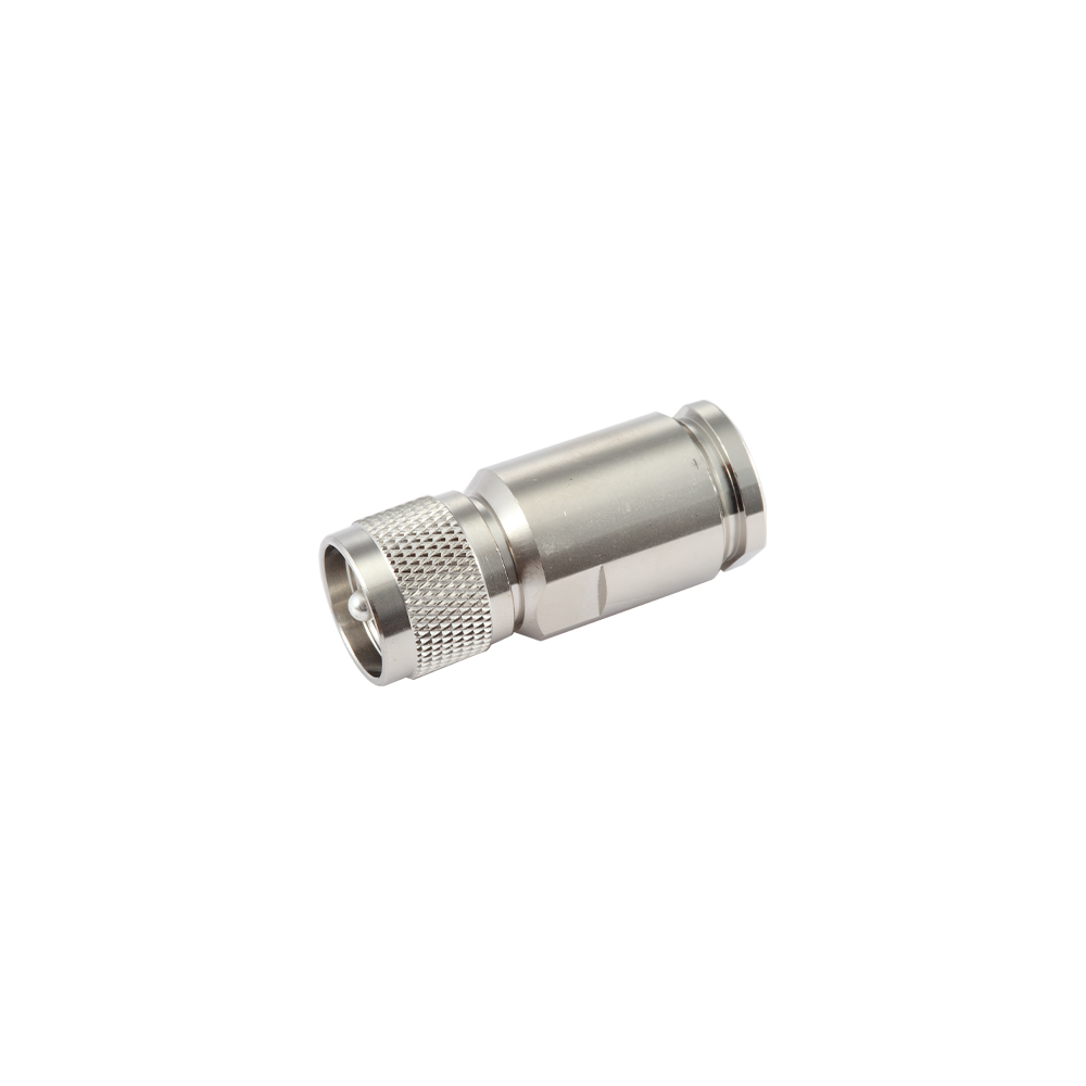
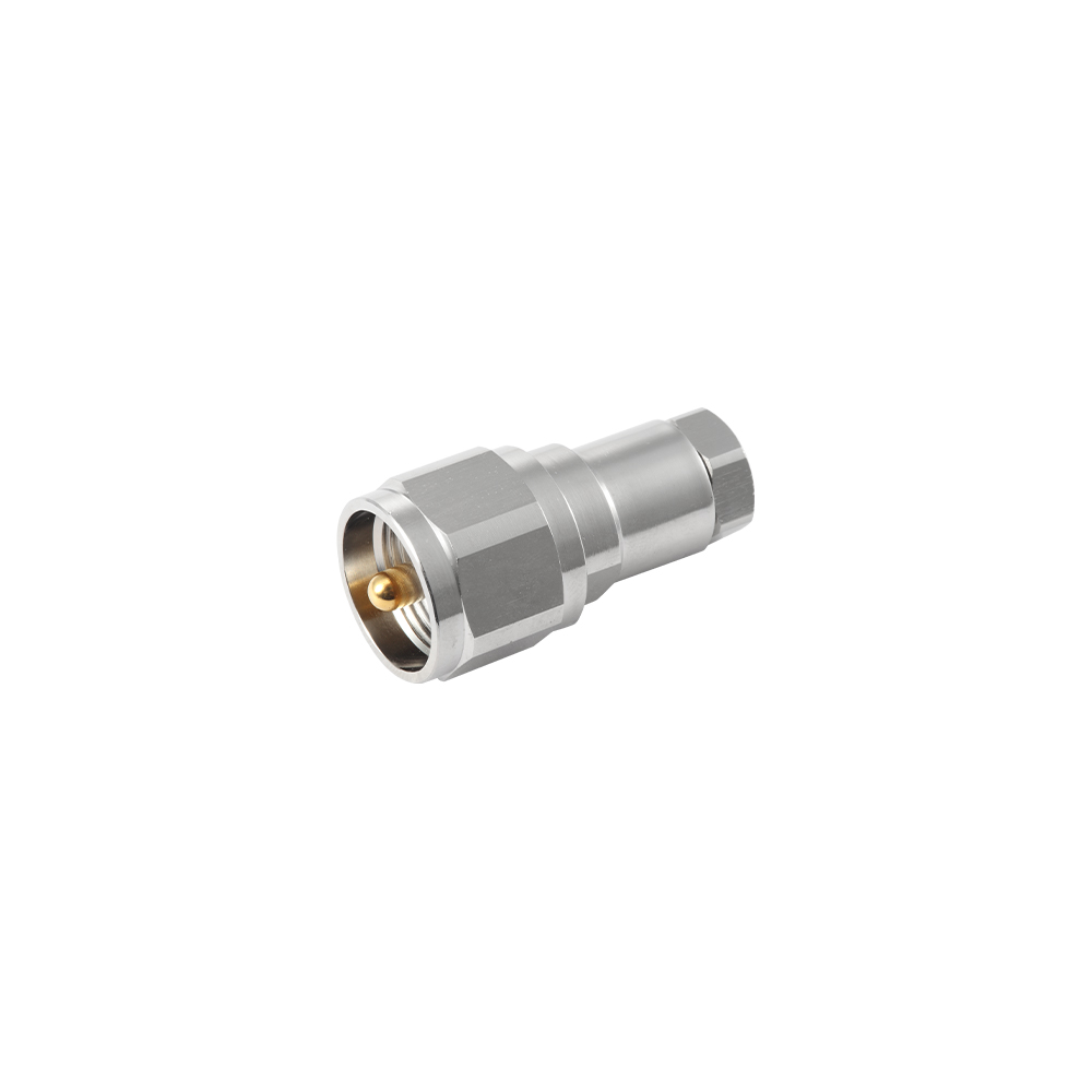
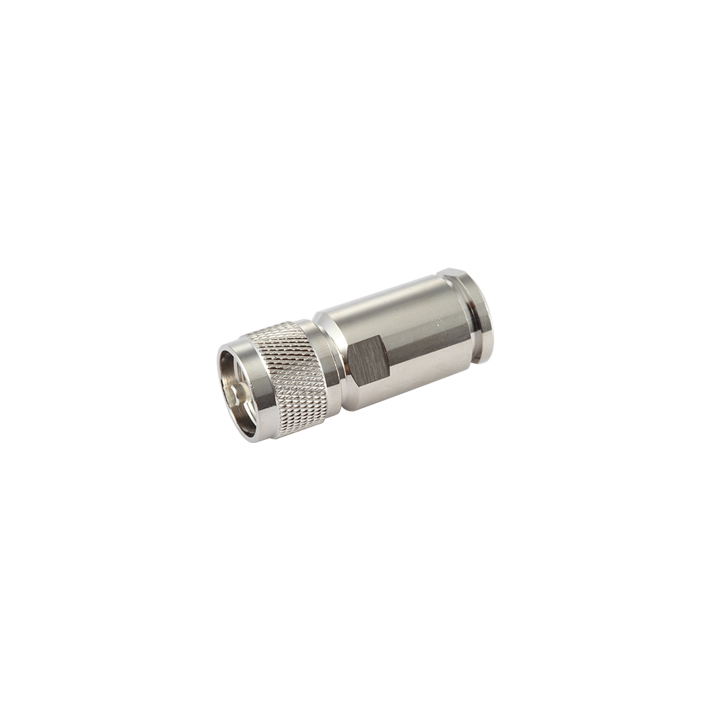
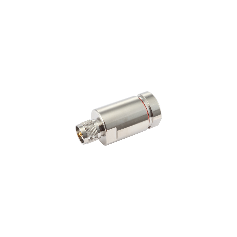
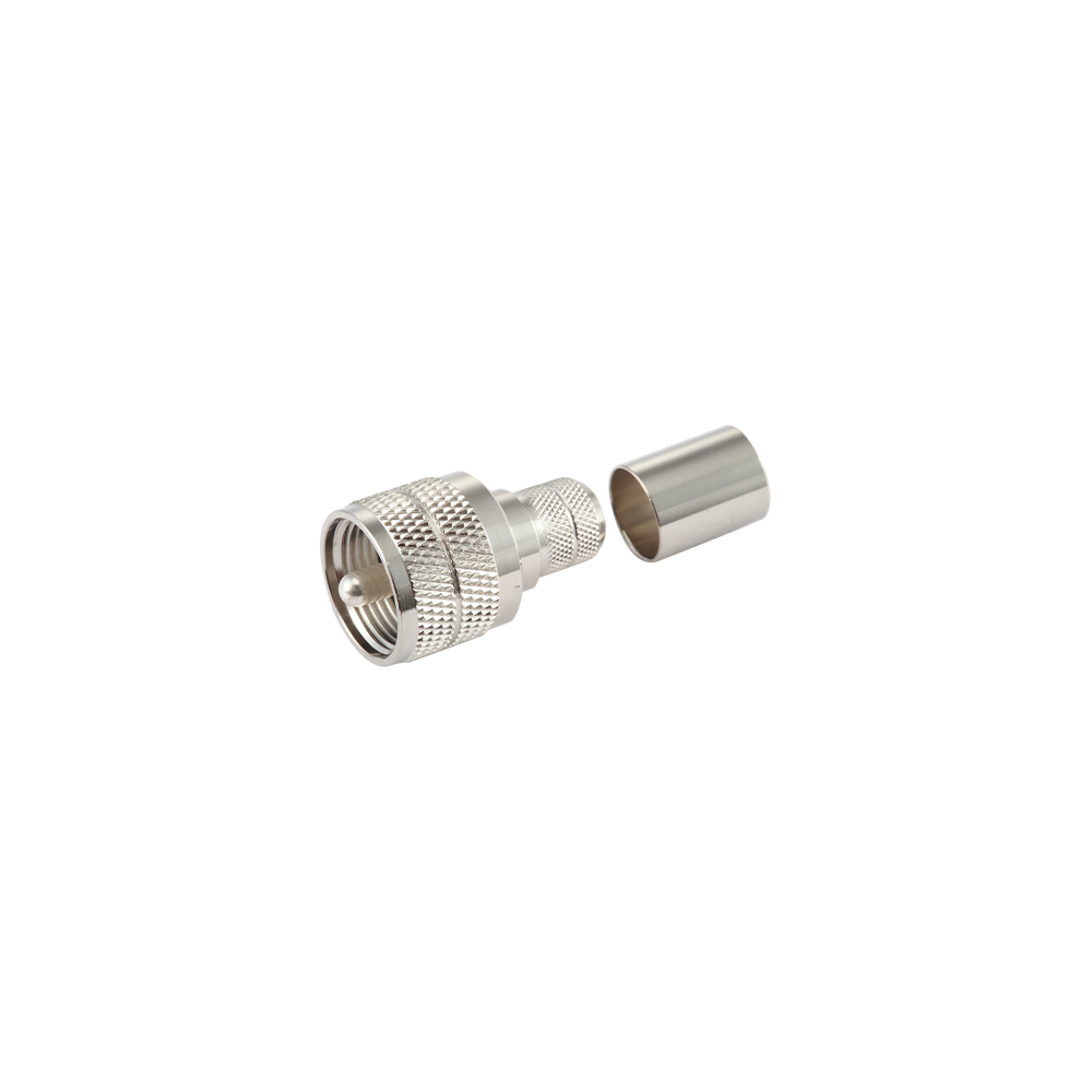
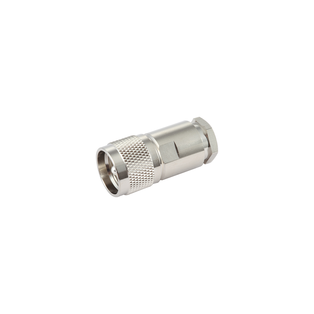
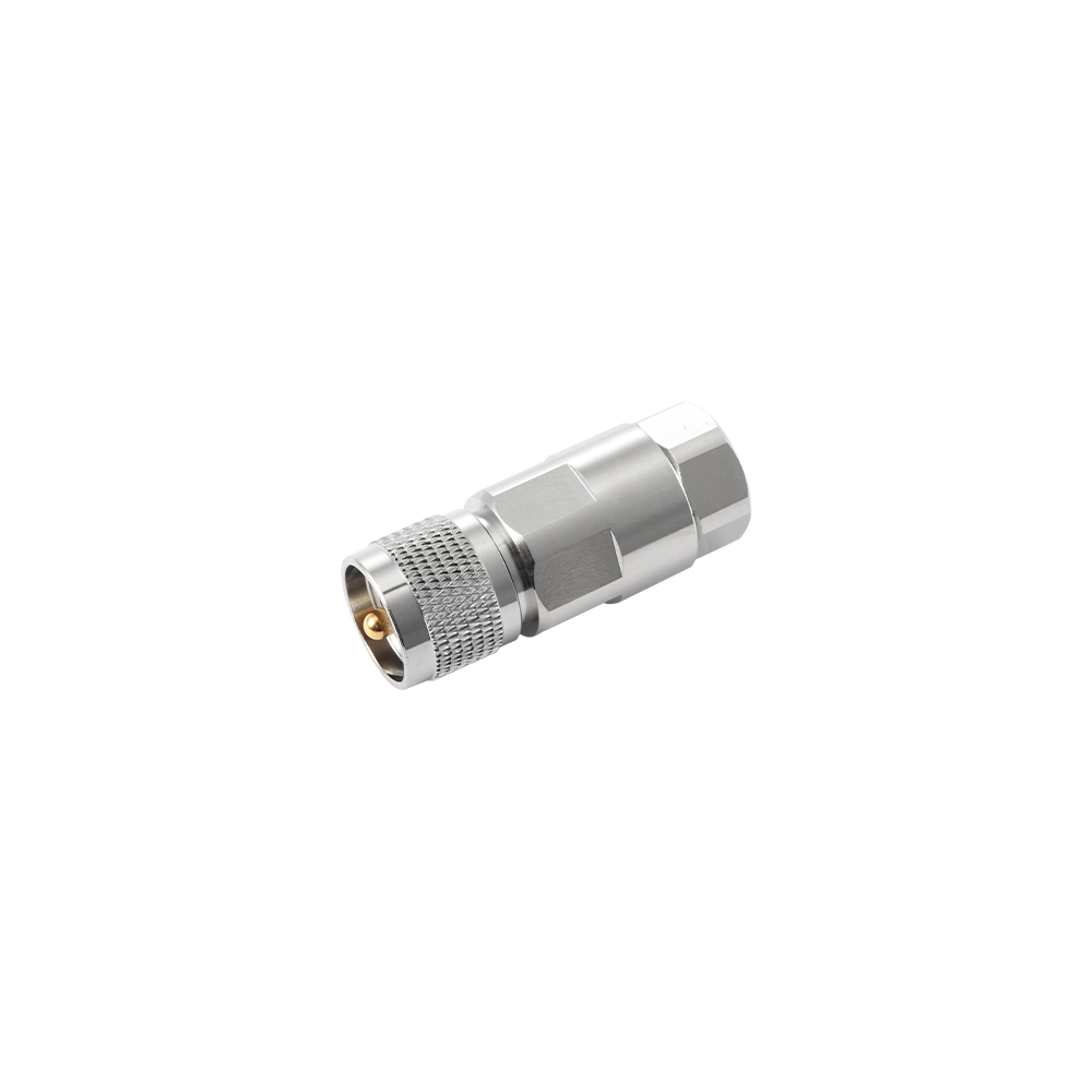
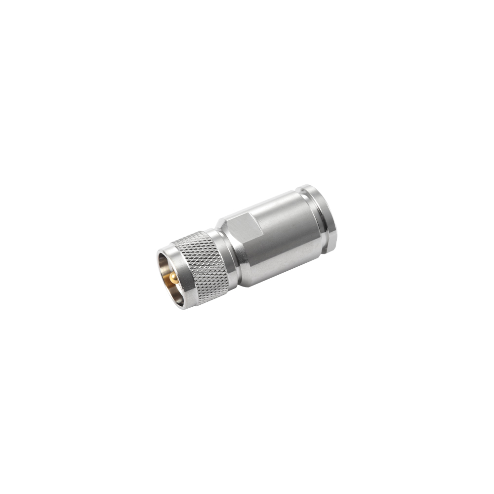
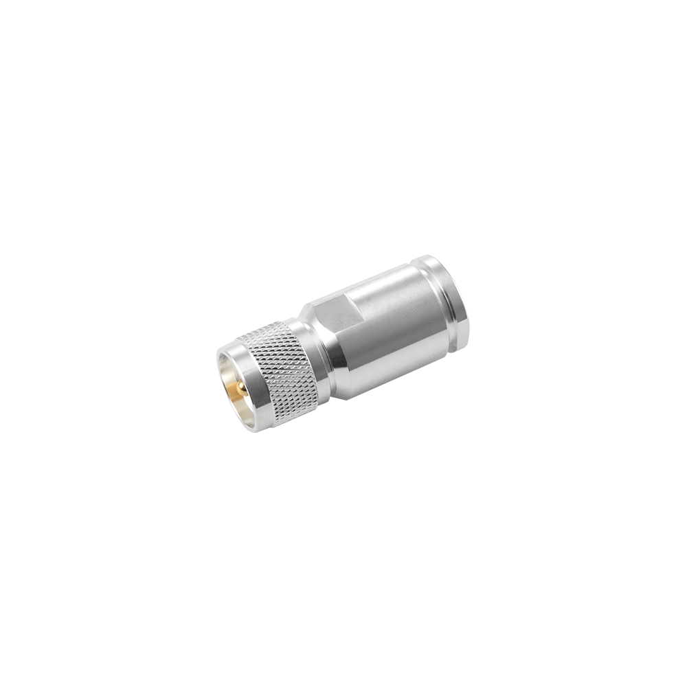
UHF RF coaxial connectors are large-body, threaded connectors used to join flexible cable to radio transceivers, antennas, and base equipment operating at lower RF frequencies. Despite the name, UHF RF coaxial connectors are rated for use up to roughly 300MHz rather than the UHF band itself, a naming convention carried over from early radio equipment. Their coupling nut and solder cup construction make them straightforward to terminate and reliable under repeated mating cycles, which keeps the series in wide use across amateur radio, marine, and land mobile systems.
The category covers straight plugs, bulkhead jacks, and right-angle variants, giving UHF RF coaxial connectors a standard interface across transceivers, antenna feed points, and patch panels built to the same mating dimensions.
Because the shell and pin dimensions have remained unchanged for decades, UHF RF coaxial connectors also remain compatible with a wide installed base of existing radio equipment, simplifying replacement and repair on systems already in service.
Working Principle
The center pin and outer shell form a coaxial signal path, with the shell also acting as the ground return and shield. Unlike connectors built to a constant-impedance profile, the dielectric section of a UHF connector has a stepped diameter, so impedance shifts somewhat with frequency; this has little effect below 300MHz but limits use at higher frequencies where precise impedance matching matters.
Coupling and Termination
A threaded coupling nut secures the plug to the jack, applying steady mechanical retention without a constant-torque requirement. Center conductors are typically soldered into a cup contact, and the outer shell is soldered or crimped to the cable braid, forming a continuous shield path from the cable into the connector body.
Application Cases
- Amateur and land mobile radio transceiver antenna connections
- Marine VHF radio feed lines and antenna mounts
- CB radio and public address system cable connections
- Broadcast and low-frequency test equipment patch panels
Yangzhou Jingcheng Electronics Co., Ltd manufactures UHF RF coaxial connectors and matched cable assemblies under MIL, IEC, and GB standards, supplying radio and communication equipment producers across multiple regions.
Comparison with Related Connectors
Compared with N-type and BNC series, UHF RF coaxial connectors cover a lower frequency range but offer a larger, low-cost solder termination that suits high-current, low-frequency radio equipment rather than precision RF test setups. Where a design calls for constant impedance at higher frequencies, N-type or BNC connectors remain the more suitable choice.
Comparison of UHF connectors with N-type and BNC series
| Parameter |
UHF |
N-type |
BNC |
| Coupling |
Threaded |
Threaded |
Bayonet |
| Frequency range |
DC–300MHz |
DC–11GHz |
DC–4GHz |
| Impedance control |
Non-constant |
Constant 50Ω |
Constant 50Ω |
| Typical use |
Amateur, marine radio |
Base stations, test gear |
Instrumentation |
Maintenance Guidance
- Inspect solder joints on the center pin and shell for cracks or cold solder after installation or repair.
- Tighten the coupling nut by hand or with light tool pressure; excessive force can crack the solder joint inside the shell.
- Apply weatherproofing tape or a boot at outdoor or marine connections to limit moisture ingress and corrosion.
- Check standing wave ratio periodically to confirm the connection has not degraded from oxidation or a loose joint.
- Store unused connectors with the mating face protected from dust, salt spray, and physical impact.
Frequently Asked Questions
Why is a UHF connector rated for lower frequencies than its name suggests?
The name dates back to early radio equipment. The stepped, non-constant impedance dielectric limits precise performance above roughly 300MHz, even though the shell design was originally associated with UHF-era equipment.
Can UHF connectors be used outdoors without additional protection?
Standard versions are not sealed against moisture, so outdoor or marine installations typically require weatherproofing tape, heat-shrink boots, or a sealed bulkhead variant.
Can custom cable assemblies be produced with UHF connectors?
Cable assemblies can be configured to cable type, length, and connector combination at each end, based on the equipment interface requirement or an existing sample.
How should a weak or noisy connection be diagnosed?
Check first that the coupling nut is fully tightened and the solder joints are intact, then measure standing wave ratio to determine whether the fault lies in the connector or elsewhere in the antenna system.


 English
 中文简体
中文简体