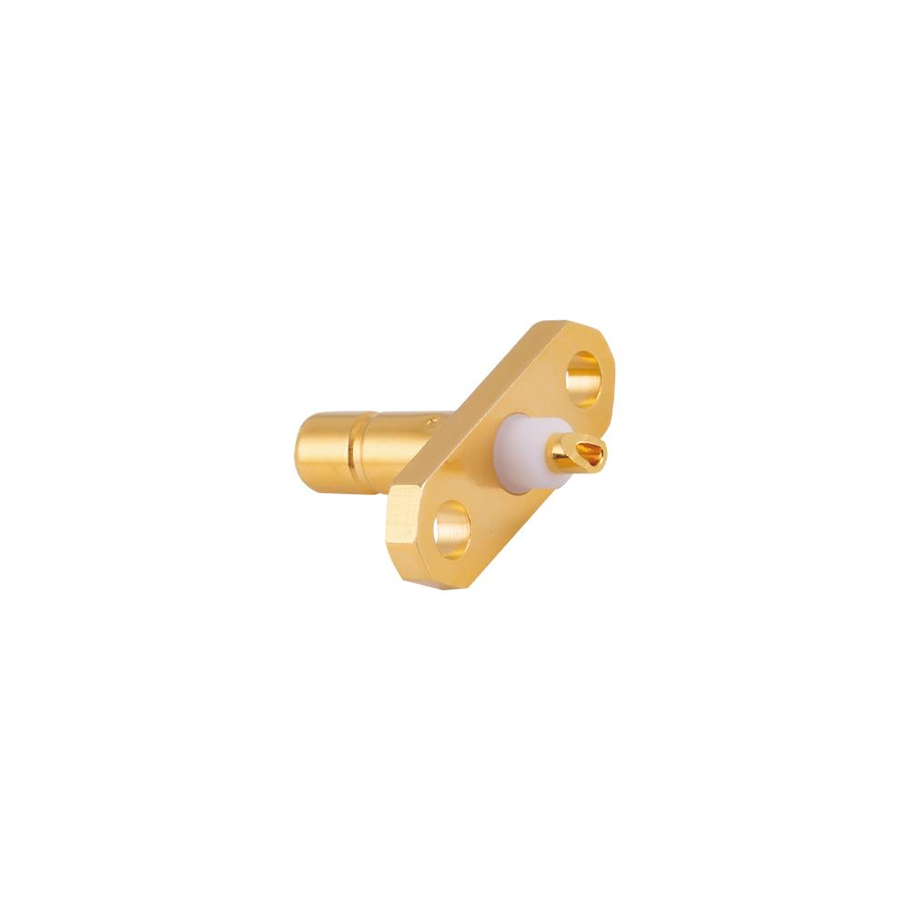
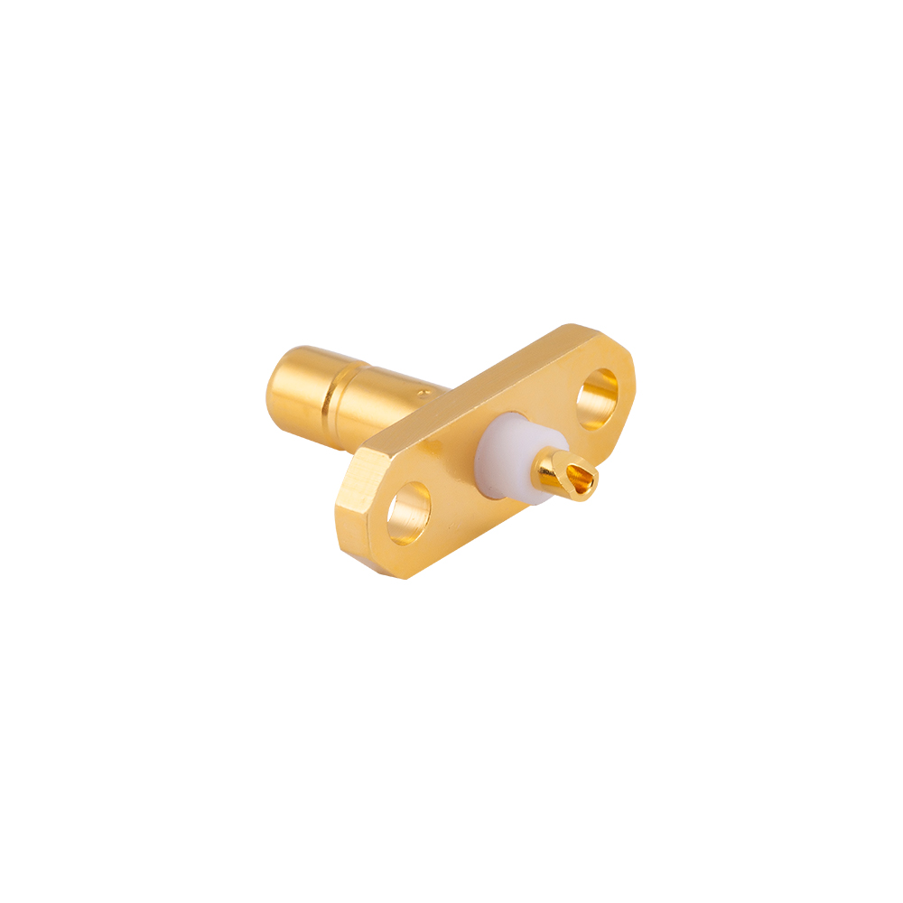
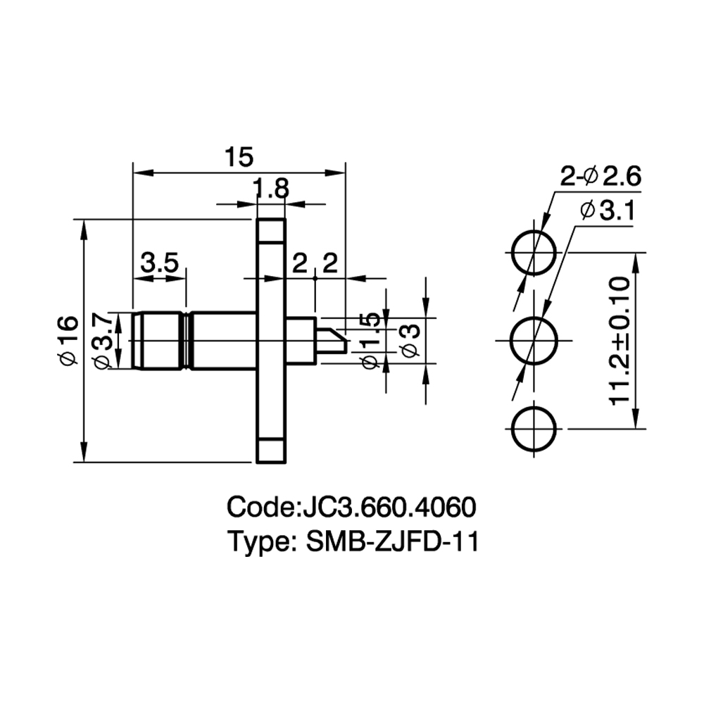
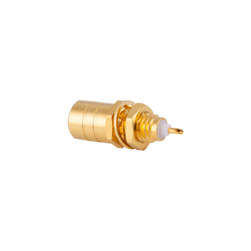
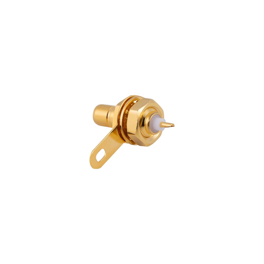
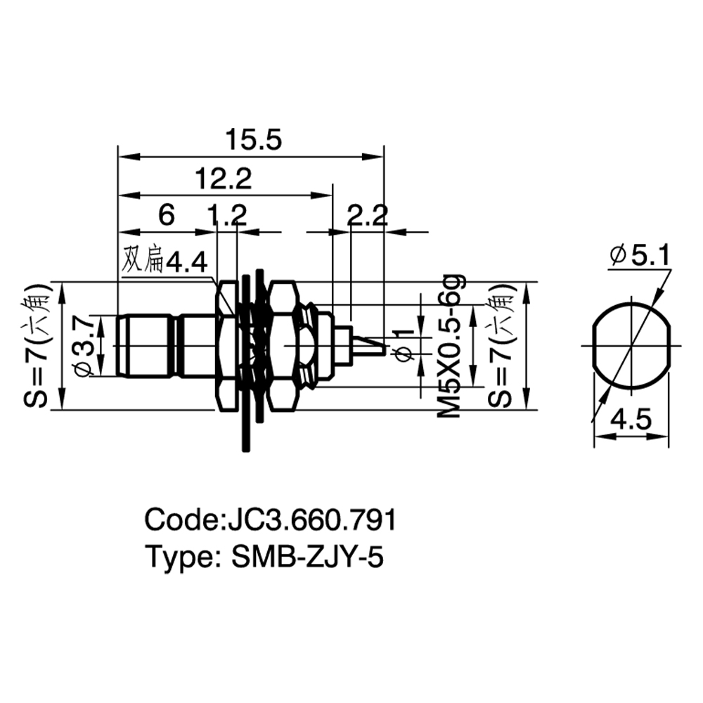
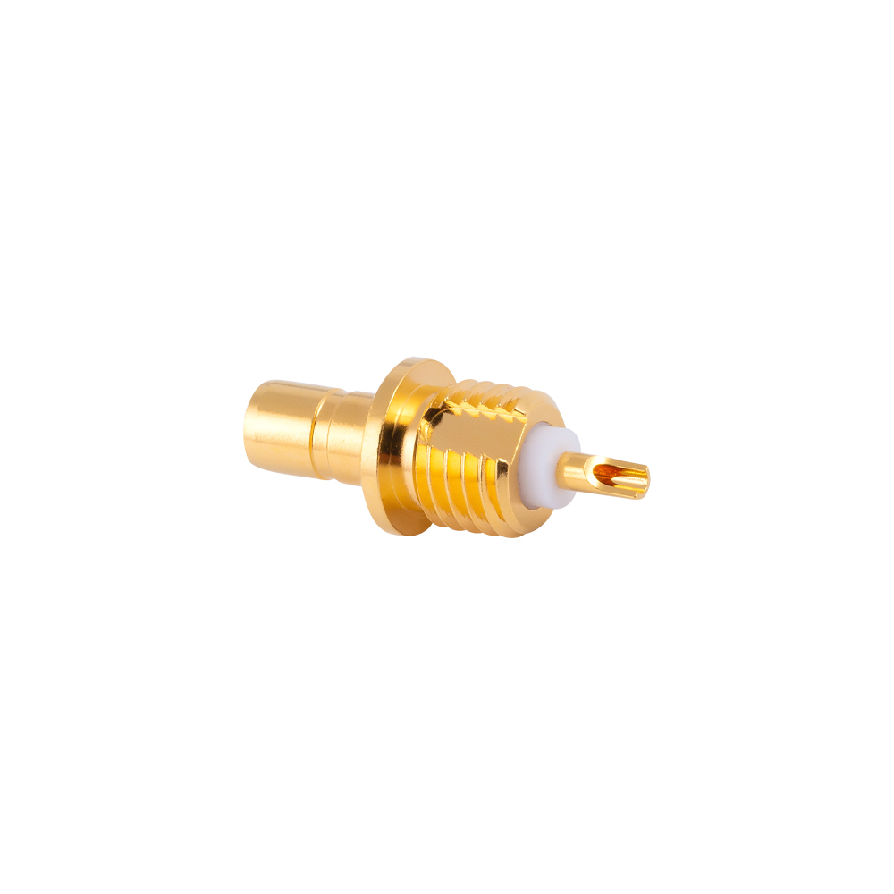
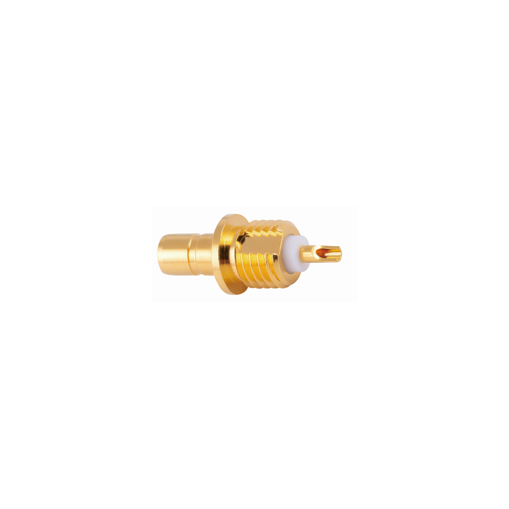
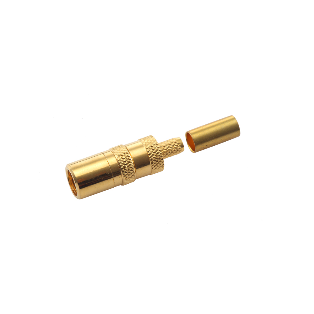
Overview & Product Commonality
SMB RF Coaxial Connectors are subminiature, snap-on coupling connectors designed for quick-connect and quick-disconnect applications in RF signal transmission. Developed as a compact alternative to larger bayonet-style interfaces, SMB connectors operate across a frequency range extending from DC to 4 GHz in standard 50-ohm configurations, with 75-ohm variants available for video and broadcast applications reaching up to 2 GHz. The defining characteristic shared by all products within this category is the push-on coupling mechanism — a spring-loaded detent system that enables tool-free mating and unmating while maintaining consistent electrical performance. This snap-on design reduces installation time, eliminates torque requirements, and provides audible tactile feedback confirming proper engagement.
Across the entire SMB product family, common attributes include a compact form factor with an outer diameter of approximately 3.7 mm at the interface, gold-plated or nickel-plated brass body construction, PTFE (polytetrafluoroethylene) dielectric insulation, and compliance with MIL-C-39012 and IEC 60169-10 interface standards. Yangzhou Jingcheng Electronics Co., Ltd. supplies SMB RF Coaxial Connectors in both 50-ohm and 75-ohm impedance versions, manufactured with precision CNC machining and tested using advanced vector network analysis equipment to verify VSWR, insertion loss, and impedance consistency across the rated frequency band. All connectors in this category share a rated operating temperature range of -65°C to +165°C and a minimum durability rating of 500 mating cycles.
The core functional purpose uniting all SMB RF Coaxial Connectors is reliable broadband RF signal interconnection where space constraints, rapid installation, and repeatable electrical performance are critical design considerations. Typical VSWR performance across the category measures ≤1.3:1 at 4 GHz for 50-ohm types, with insertion loss maintained below 0.3 dB through precision dimensional control of the inner conductor and dielectric support structure.
Core Characteristics Shared Across All SMB Connectors:
- Snap-on / push-on coupling mechanism — no threading required
- Compact subminiature form factor with approximately 3.7 mm outer contact diameter
- 50Ω and 75Ω impedance options available across the product range
- Frequency coverage: DC–4 GHz (50Ω) / DC–2 GHz (75Ω)
- Brass body with gold or nickel plating; PTFE dielectric insulation
- Compliant with MIL-C-39012 and IEC 60169-10 interface specifications
- Operating temperature: -65°C to +165°C; durability ≥500 mating cycles
- Typical VSWR ≤1.3:1 at rated frequency; insertion loss ≤0.3 dB
Common Types & Configurations
SMB RF coaxial connectors are manufactured in multiple physical configurations to accommodate diverse installation requirements. The table below summarizes the standard types available, each sharing the same snap-on interface geometry while differing in mounting method and body orientation.
| Type Designation |
Mounting Style |
Body Orientation |
Key Features |
Typical Cable Compatibility |
| SMB Straight Plug |
Cable mount — solder/clamp or crimp |
Straight |
Male contact pin; snap-on outer sleeve; most common field-installable type |
RG-174, RG-316, RG-188, LMR-100 |
| SMB Straight Jack |
Cable mount — solder/clamp or crimp |
Straight |
Female socket contact; mates with SMB plug; cable-entry at rear |
RG-174, RG-316, RG-188, LMR-100 |
| SMB Bulkhead Jack |
Panel mount — bulkhead feed-through |
Straight |
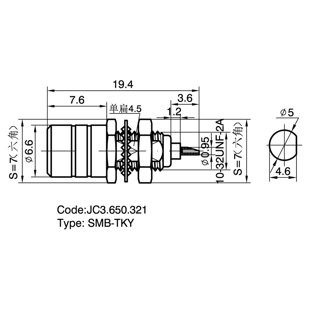
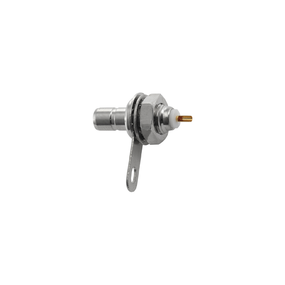
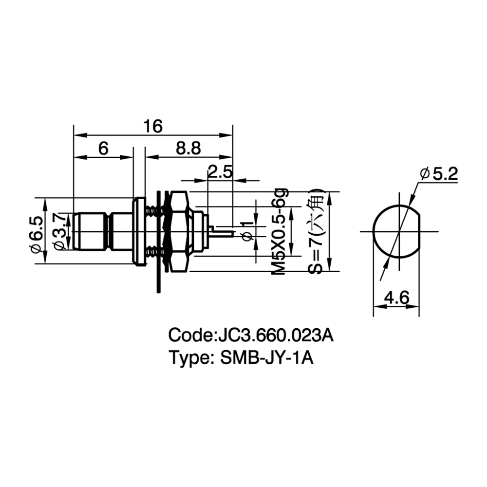
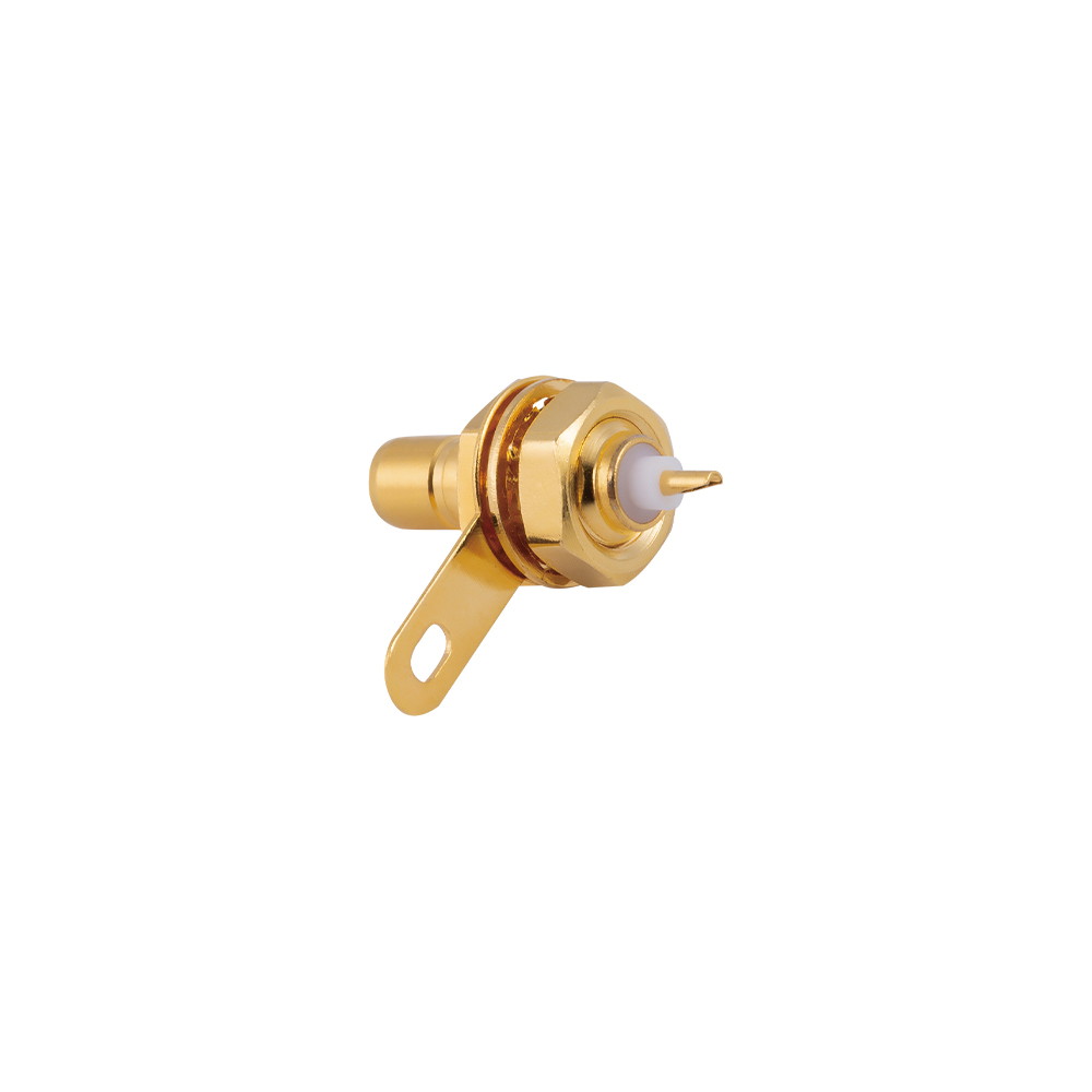
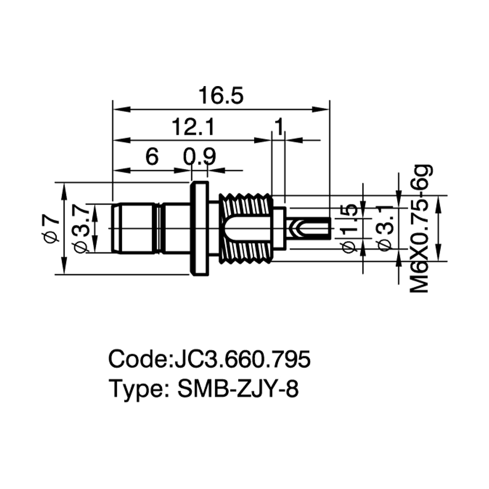
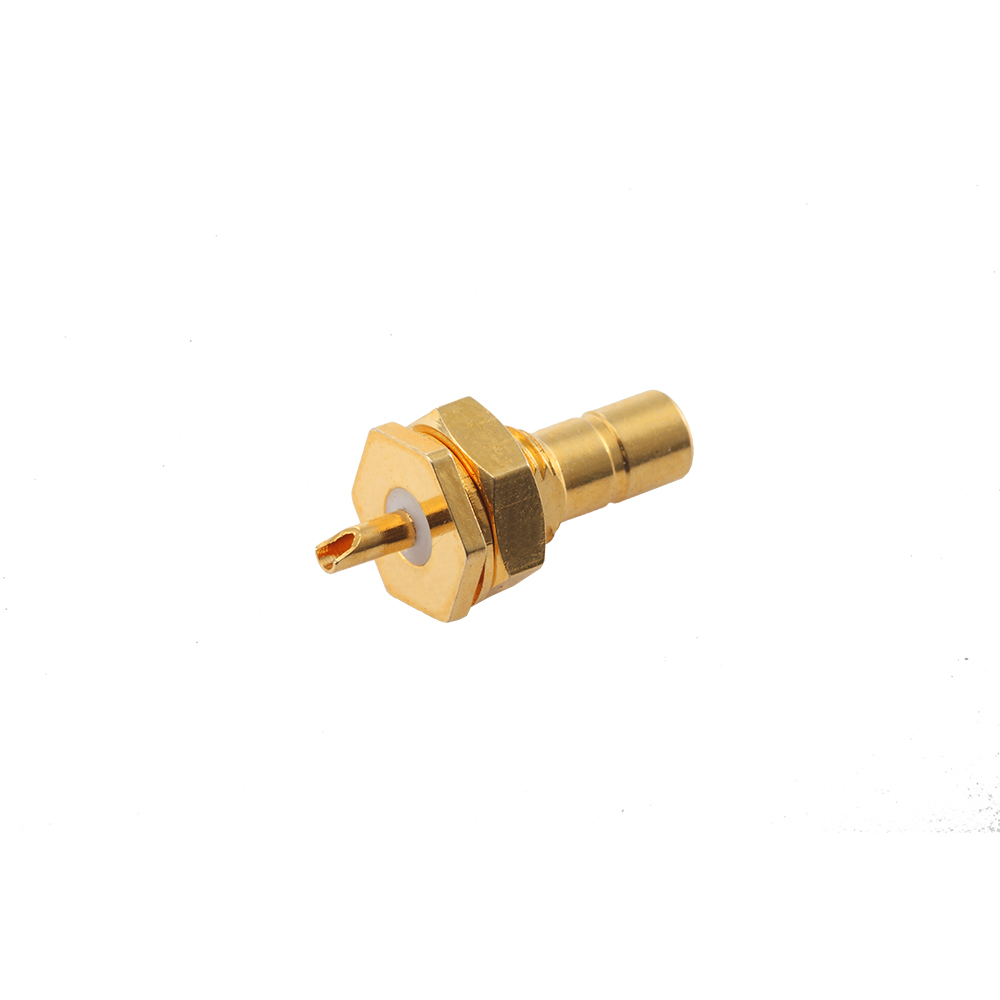
Threaded body for panel mounting; nut and lock washer included; sealed variants available |
RG-174, RG-316, semi-rigid cable |
| SMB PCB Mount Jack |
PCB mount — through-hole or surface mount |
Straight or right-angle |
Solder legs for direct PCB attachment; right-angle versions conserve board space |
N/A (direct PCB termination) |
| SMB Right-Angle Plug |
Cable mount — solder/clamp or crimp |
90° right-angle |
Reduces installed height in tight enclosures; maintains full electrical performance |
RG-174, RG-316, RG-188 |
| SMB Right-Angle Jack |
Cable mount or PCB mount |
90° right-angle |
Space-saving female receptacle; suitable for tight routing environments |
RG-174, RG-316, or PCB pins |
Comparison: SMB vs. Related RF Connector Series
Understanding how SMB connectors compare to other common RF coaxial connector families aids in proper component selection. The comparison below highlights key differentiating parameters across coupling mechanism, frequency capability, physical size, and typical application domains.
| Parameter |
SMB |
SMA |
MCX |
SMC |
BNC |
| Coupling Mechanism |
Snap-On (Push) |
Threaded (Screw) |
Snap-On (Push) |
Threaded (Screw) |
Bayonet (Twist-Lock) |
| Frequency Range (50Ω) |
DC – 4 GHz |
DC – 18 GHz (typ.) |
DC – 6 GHz |
DC – 10 GHz |
DC – 4 GHz |
| Impedance Options |
50Ω / 75Ω |
50Ω |
50Ω / 75Ω |
50Ω |
50Ω / 75Ω |
| Outer Diameter (approx.) |
~3.7 mm |
~4.1 mm (1/4-36 thread) |
~3.6 mm |
~3.8 mm (10-32 thread) |
~9.5 mm |
| Mating Speed |
Fast (push-on) |
Moderate (threaded) |
Fast (push-on) |
Moderate (threaded) |
Fast (bayonet) |
| Typical Applications |
Automotive, GPS, Telecom, Medical |
Microwave, Test Equipment, Mil-Aero |
GPS, WLAN, Consumer Devices |
Radar, Microwave Links |
Broadcast, Video, Instrumentation |
* SMB column highlighted for quick identification. Performance figures represent typical industry-standard values; specific products may vary by manufacturer.
Technical Specifications — SMB Connector Series
| Specification |
50Ω Version |
75Ω Version |
| Frequency Range |
DC – 4 GHz |
DC – 2 GHz |
| Characteristic Impedance |
50 Ω |
75 Ω |
| VSWR (max, at rated freq.) |
≤ 1.3:1 @ 4 GHz |
≤ 1.35:1 @ 2 GHz |
| Insertion Loss (typ.) |
≤ 0.3 dB @ 4 GHz |
≤ 0.2 dB @ 2 GHz |
| Insulation Resistance |
≥ 5,000 MΩ |
≥ 5,000 MΩ |
| Dielectric Withstanding Voltage |
1,000 V rms (at sea level) |
750 V rms (at sea level) |
| Contact Resistance (Center) |
≤ 6 mΩ |
≤ 10 mΩ |
| Contact Resistance (Outer) |
≤ 2 mΩ |
≤ 3 mΩ |
| Temperature Range |
-65°C to +165°C |
-65°C to +165°C |
| Mating Durability |
≥ 500 cycles |
≥ 500 cycles |
| Body Material |
Brass (gold or nickel plated) |
Brass (gold or nickel plated) |
| Center Contact Material |
Beryllium copper / brass (gold plated) |
Beryllium copper / brass (gold plated) |
| Dielectric Material |
PTFE (Polytetrafluoroethylene) |
PTFE (Polytetrafluoroethylene) |
| Applicable Standards |
MIL-C-39012, IEC 60169-10 |
MIL-C-39012, IEC 60169-10 |
Application Scenarios
SMB connectors are deployed across a wide spectrum of industries where reliable RF interconnection, compact packaging, and fast installation are essential. The snap-on coupling design makes them particularly suited to applications requiring frequent connection and disconnection without specialized tooling.
| Industry Sector |
Typical Equipment / System |
Role of SMB Connector |
| Automotive Electronics |
GPS antennas, telematics modules, in-vehicle infotainment, ADAS sensors |
Compact snap-on interface for dashboard and roof-mounted antenna connections; vibration-resistant retention |
| Telecommunications |
Base station equipment, repeater modules, small-cell infrastructure |
Internal RF interconnects within shielded enclosures; quick assembly during manufacturing and field service |
| Wireless & GPS Systems |
GPS receivers, wireless LAN access points, RFID readers |
Low-loss antenna feed connections; 75Ω variants for GPS L-band signal paths |
| Test & Measurement |
Spectrum analyzers, signal generators, network analyzers, RF probes |
Repeatable test-port connections; durability for frequent connect/disconnect cycles |
| Medical Devices |
Diagnostic imaging equipment, patient monitoring, RF ablation systems |
Secure snap-on connections in space-constrained medical enclosures; reliable signal integrity |
| Industrial & Instrumentation |
Remote monitoring units, process control transmitters, IoT gateways |
Rugged RF interconnection for industrial environments; wide operating temperature tolerance |
Selection Guide & Key Considerations
Selecting the appropriate SMB connector for a specific application requires evaluation of several interrelated parameters. The following decision points guide engineers and procurement specialists toward an optimal choice. Yangzhou Jingcheng Electronics Co., Ltd. provides technical consultation to assist with connector selection, leveraging decades of RF component expertise and in-house testing capability up to 50 GHz for related product lines.
- Impedance Matching: Confirm whether the system requires 50Ω (standard for most RF and wireless applications) or 75Ω (common in video, broadcast, and certain GPS receiver front-ends). Mismatched impedance causes signal reflections and increased VSWR.
- Frequency Verification: Verify that the connector's rated frequency range covers the highest operating frequency in the system with adequate margin. Standard 50Ω SMB connectors perform to 4 GHz; for applications approaching this limit, review VSWR and insertion loss curves.
- Mounting Configuration: Determine whether a cable-mount plug/jack, bulkhead panel-mount jack, or PCB-mount receptacle suits the physical layout. Right-angle variants reduce installed height in compact enclosures.
- Cable Compatibility: Match the connector's cable-entry design to the specific coaxial cable type (e.g., RG-174, RG-316, RG-188, LMR-100, or semi-rigid cables). Crimp-style, clamp-style, and solder-style terminations are available.
- Plating Specification: Select between gold plating (superior corrosion resistance and conductivity, recommended for high-reliability and outdoor applications) and nickel plating (cost-effective for indoor and commercial use). Center contacts are typically gold-plated beryllium copper for consistent spring force.
- Environmental Conditions: Consider temperature extremes, humidity exposure, and potential vibration. SMB connectors with silicone gaskets or sealed bulkhead designs offer enhanced environmental protection for outdoor installations.
- Mating Cycle Requirements: For applications with frequent connect/disconnect operations, verify the connector's durability rating (≥500 cycles standard) and consider gold-plated interfaces to minimize wear-related performance degradation.
- Standards Compliance: Ensure the selected connector meets applicable interface standards (MIL-C-39012, IEC 60169-10) for dimensional and electrical interchangeability with mating connectors from compliant manufacturers.
Frequently Asked Questions
Q1: What is the primary difference between SMB and SMA connectors?
The fundamental distinction lies in the coupling mechanism. SMB connectors utilize a snap-on (push-on) interface that enables rapid connection and disconnection without threading, while SMA connectors employ a threaded screw coupling that provides a more mechanically robust connection suitable for higher frequencies (typically to 18 GHz and beyond). SMB connectors are preferred when installation speed and frequent mating cycles are priorities; SMA connectors are favored in applications demanding maximum mechanical stability and extended high-frequency performance. The two series are not mechanically interchangeable.
Q2: Can SMB connectors be used interchangeably between 50Ω and 75Ω systems?
No. Although 50Ω and 75Ω SMB connectors may appear physically similar, the internal dimensions of the center conductor and dielectric support differ to achieve the target characteristic impedance. Using a 50Ω plug with a 75Ω jack (or vice versa) creates an impedance discontinuity at the interface, resulting in elevated VSWR and signal reflection. For applications requiring impedance transition, a dedicated impedance-matching adapter should be used rather than forcing an incompatible connection. Yangzhou Jingcheng Electronics supplies both impedance versions with clear labeling to prevent misidentification.
Q3: What is the typical insertion loss of an SMB connector at 4 GHz?
A properly terminated 50Ω SMB connector typically exhibits insertion loss of ≤0.3 dB at 4 GHz when measured as a mated pair. Actual performance depends on connector design quality, plating material, surface finish, and the precision of the cable termination. Gold-plated center contacts and high-quality PTFE dielectric supports contribute to minimizing insertion loss across the operating band.
Q4: Are SMB connectors suitable for outdoor applications?
SMB connectors can be deployed in outdoor environments when properly specified. Key considerations include selecting connectors with appropriate plating (gold plating offers superior corrosion resistance), utilizing bulkhead variants with sealing gaskets for enclosure feed-through points, and considering the addition of weatherproof boots or heat-shrink tubing over the cable-connector junction. The standard operating temperature range of -65°C to +165°C accommodates most outdoor thermal conditions. For direct weather exposure, however, connectors specifically rated with IP67 or similar ingress protection should be evaluated.
Q5: How does the SMB snap-on mechanism maintain reliable contact under vibration?
The SMB snap-on coupling employs a spring-loaded detent ring in the plug body that engages a corresponding groove on the jack's outer conductor. This spring mechanism provides a consistent radial clamping force that resists unintentional decoupling under vibration. When mated, the spring detent produces an audible click, giving the installer positive confirmation of full engagement. For extreme vibration environments, additional retention features such as secondary locking clips can be considered, though these are not part of the standard SMB interface definition.
Q6: What cable types are commonly terminated with SMB connectors?
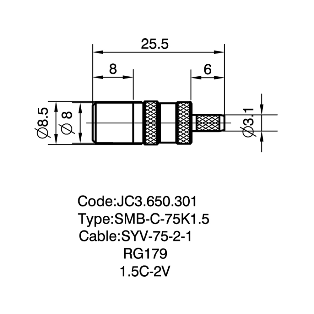
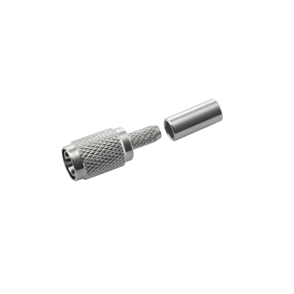
SMB connectors are designed for small-diameter flexible and semi-rigid coaxial cables. Common flexible cable types include RG-174 (50Ω, Ø2.8mm), RG-316 (50Ω, Ø2.5mm), RG-188 (50Ω, Ø2.6mm), and LMR-100 (50Ω, Ø2.8mm). For 75Ω applications, miniature 75Ω coaxial cables such as RG-179 are frequently used. Semi-rigid cables with diameters in the 2.2mm to 3.6mm range (such as UT-085 or UT-141) can also be terminated with SMB connectors using solder-type cable-entry designs. Yangzhou Jingcheng Electronics provides SMB cable connectors with crimp ferrules sized for specific cable diameters to ensure consistent termination quality.
Q7: How should SMB connectors be cleaned and maintained?
Periodic inspection of the contact surfaces for debris, oxidation, or wear is recommended, particularly in high-cycle applications. Cleaning can be performed using isopropyl alcohol and lint-free swabs on accessible contact areas. Compressed air may be used to remove loose particles from the interface. Avoid abrasive cleaning methods that could damage the gold plating. Connectors showing visible wear on the spring detent or center contact should be replaced to maintain specified electrical performance.


 English
 中文简体
中文简体