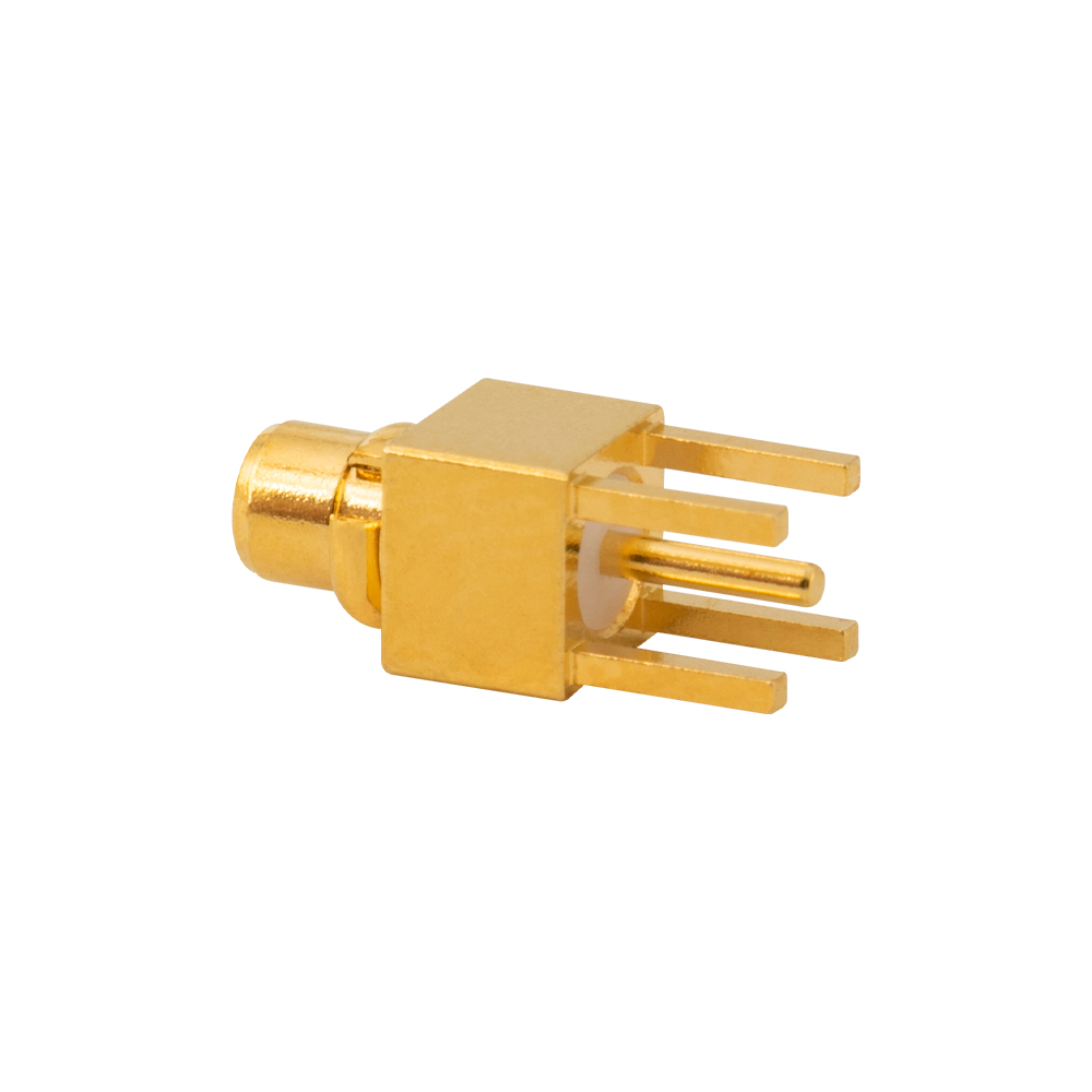
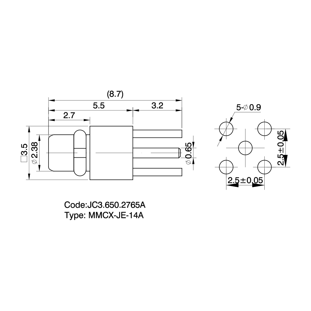
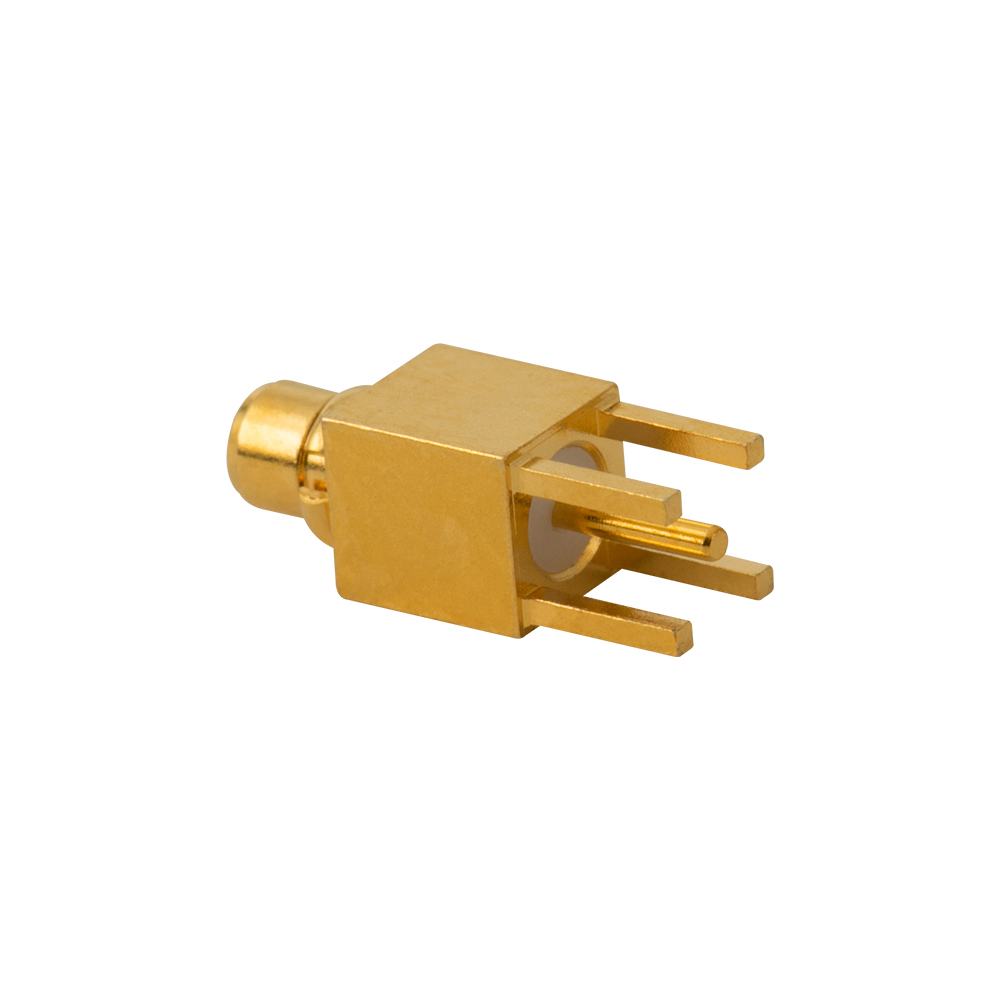
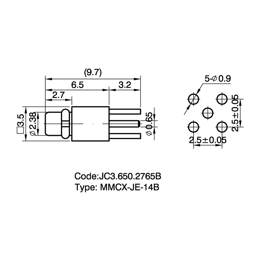
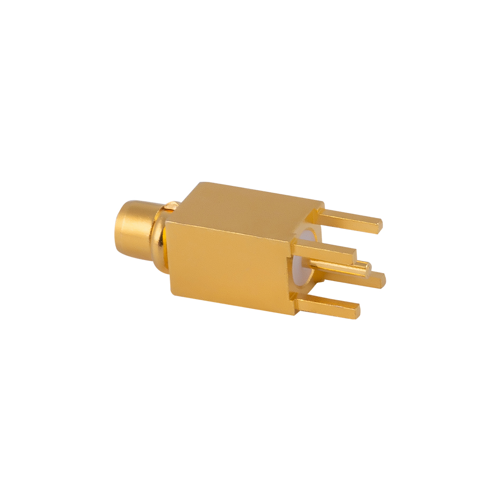
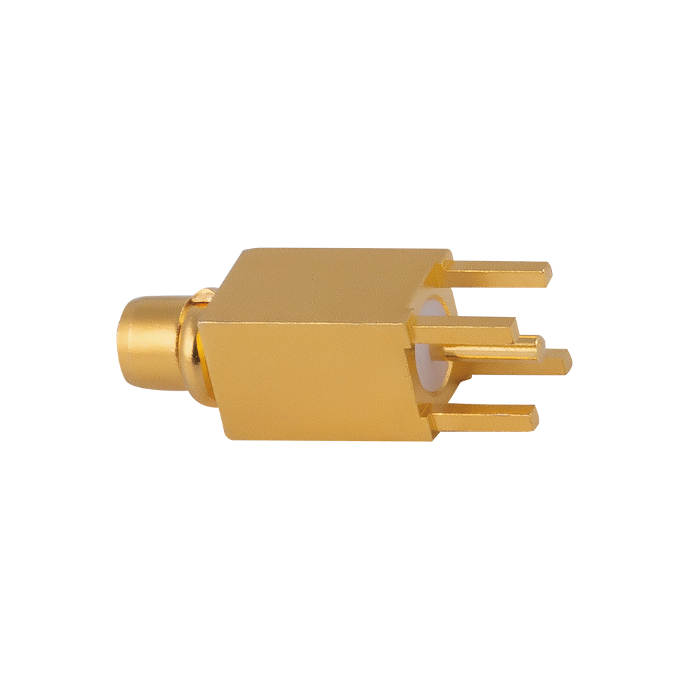
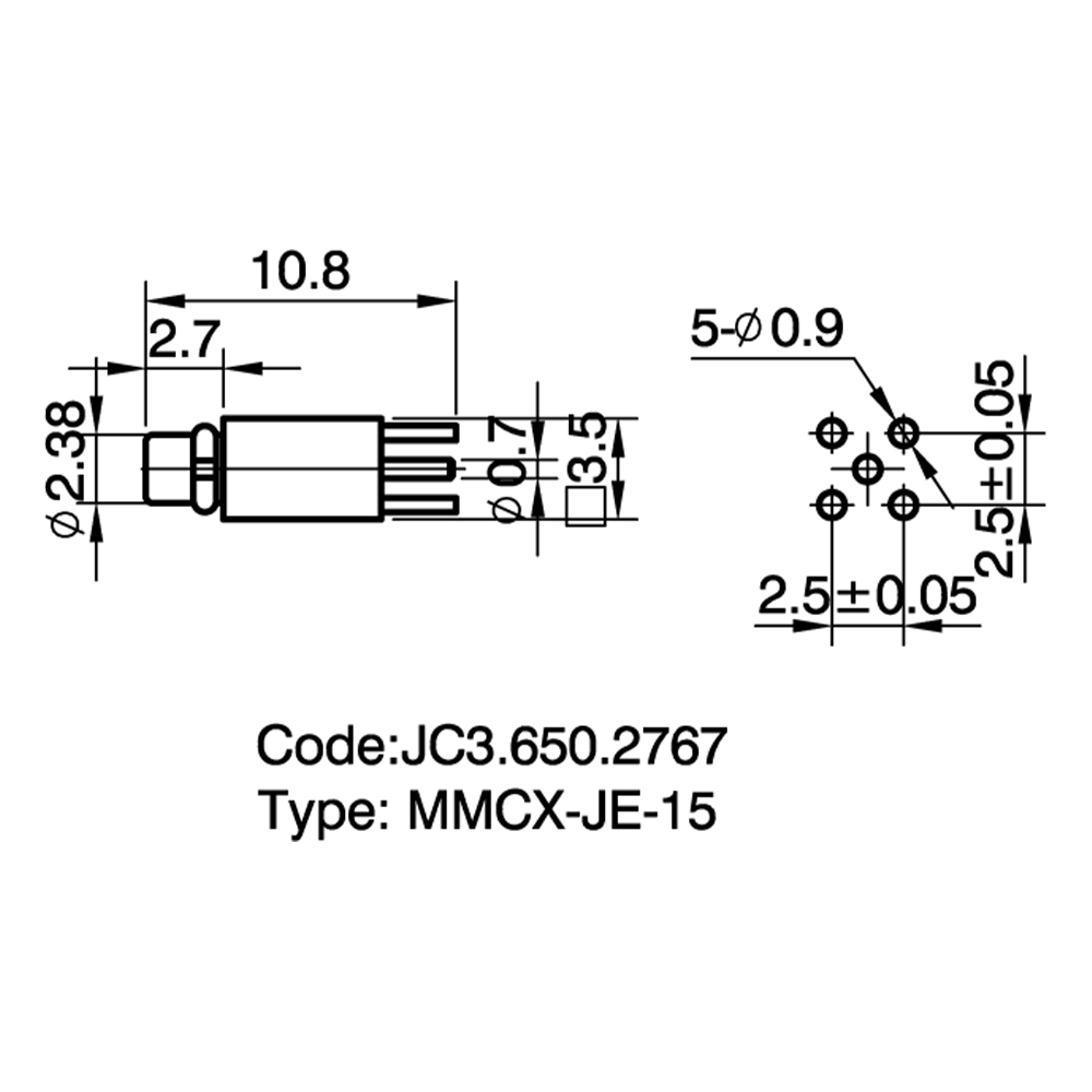
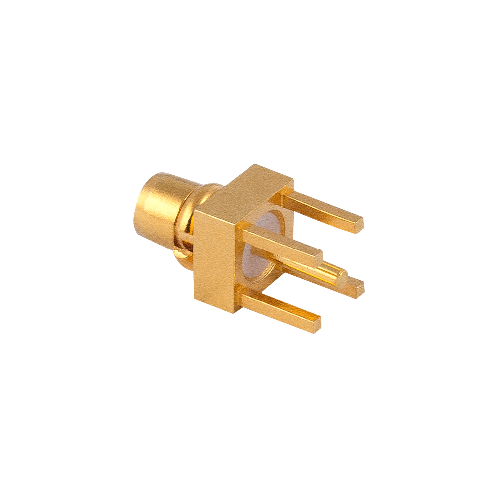
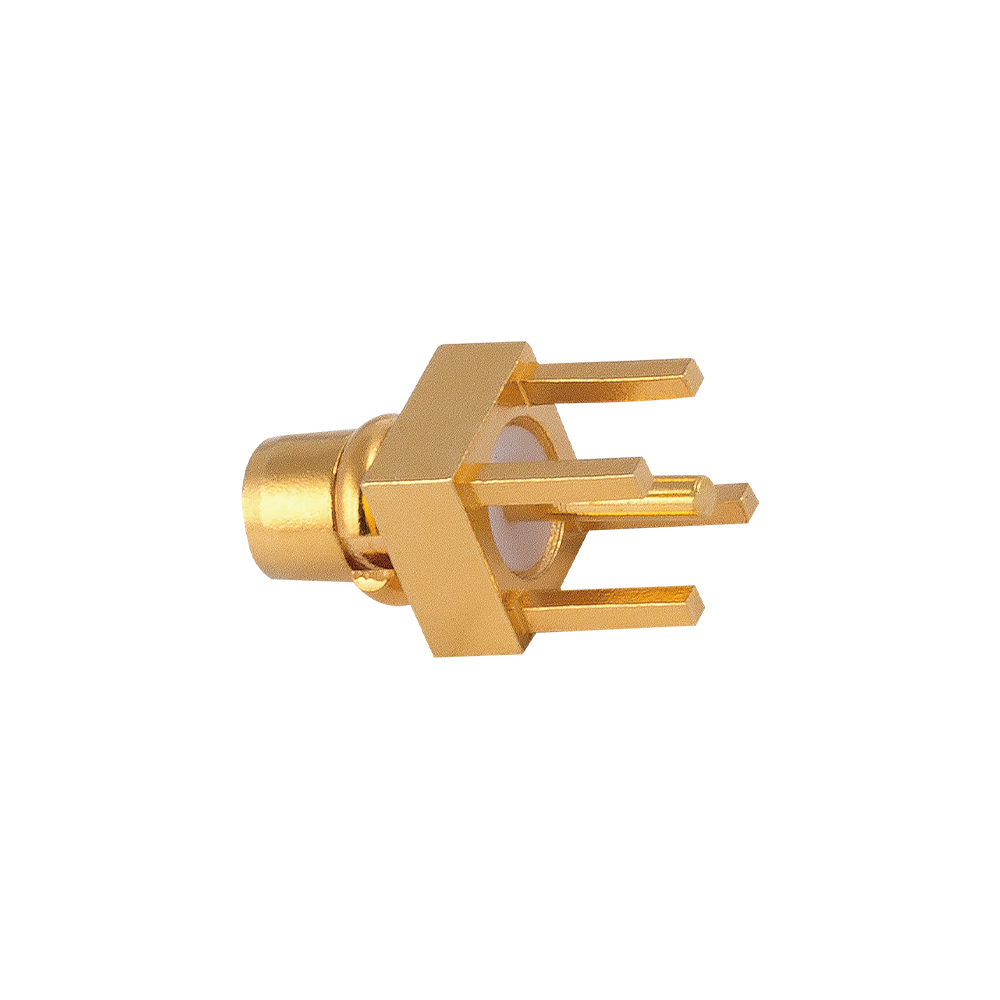
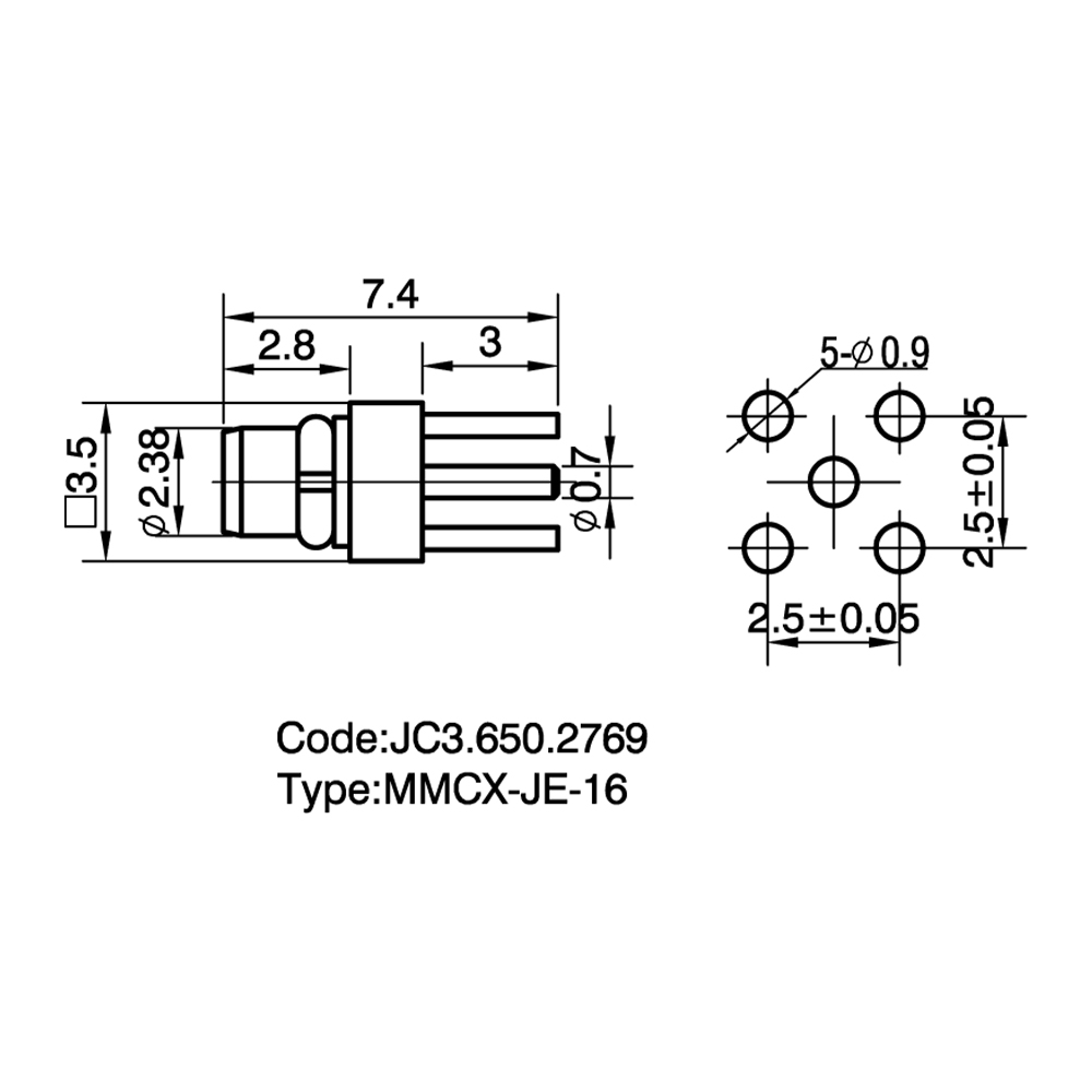
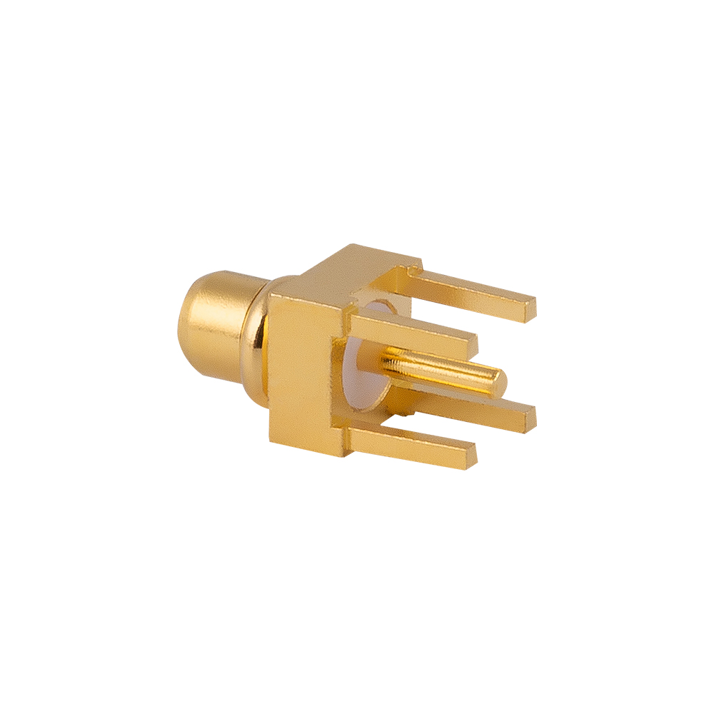
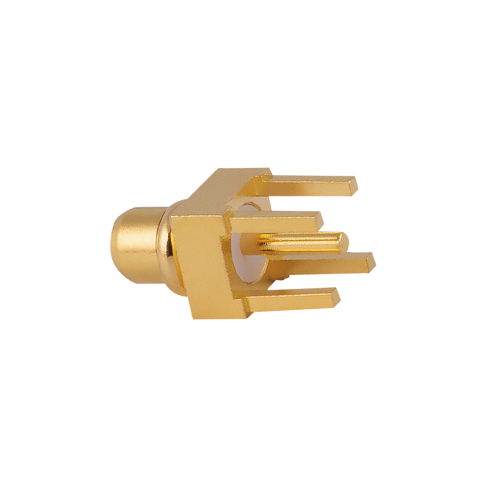
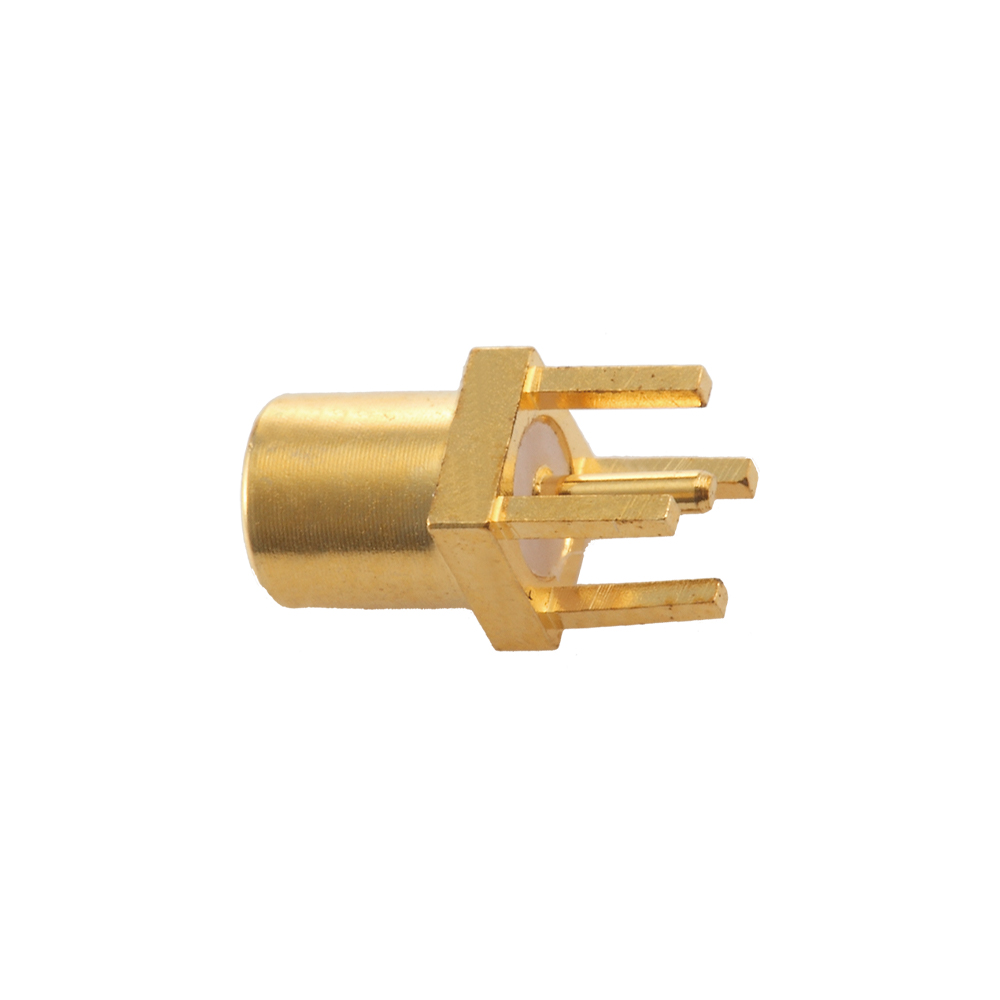
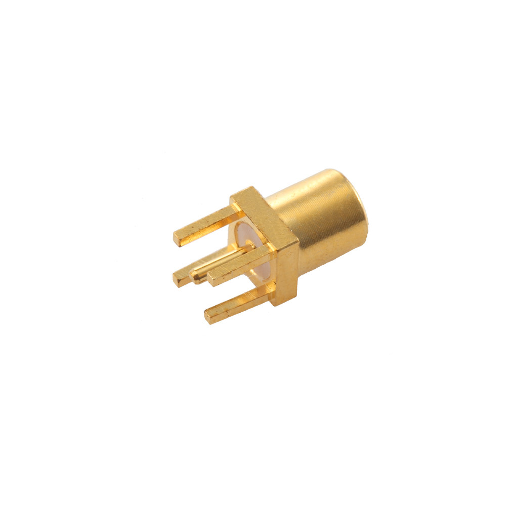
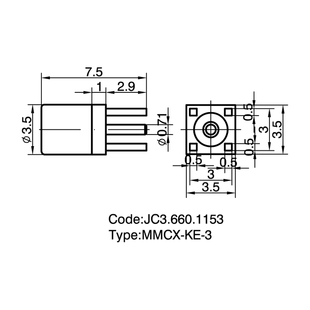
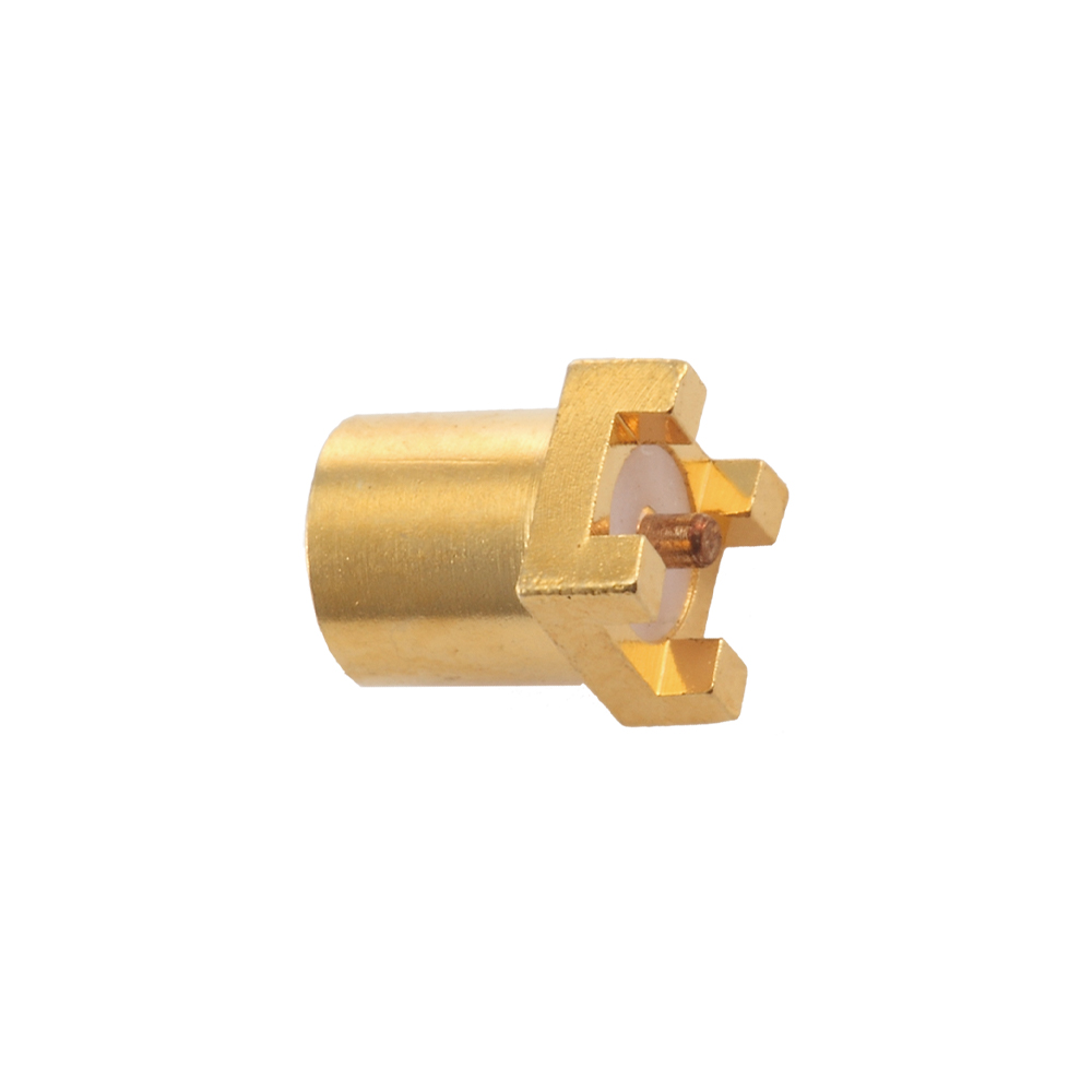
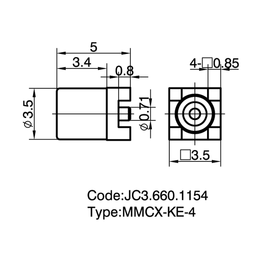
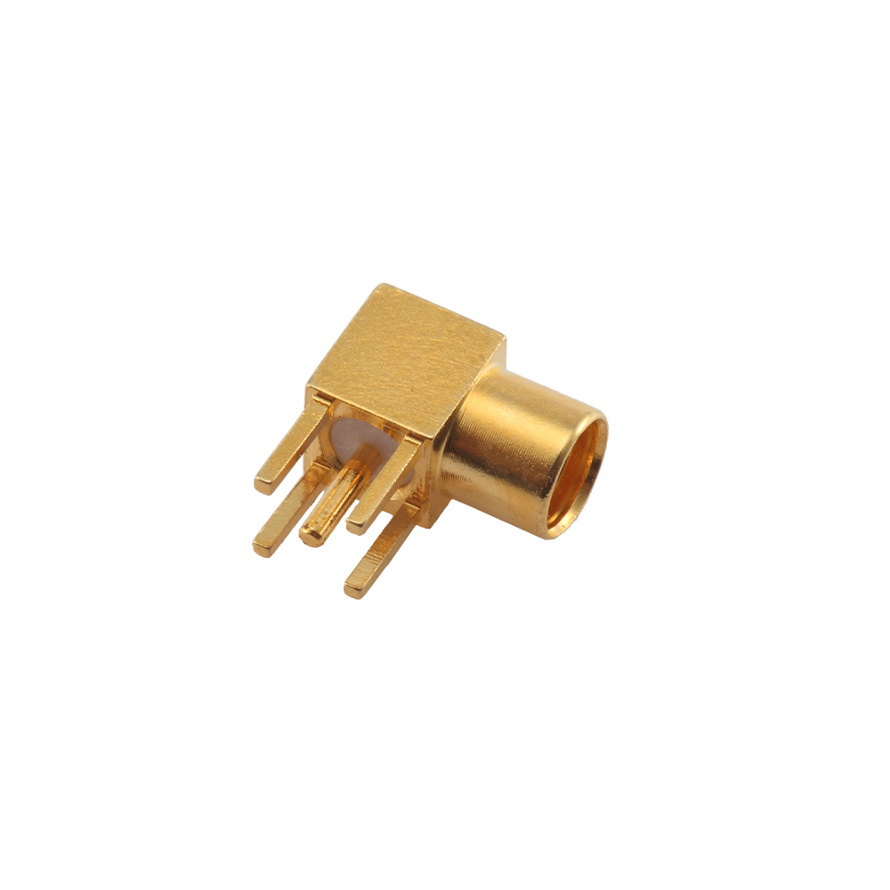
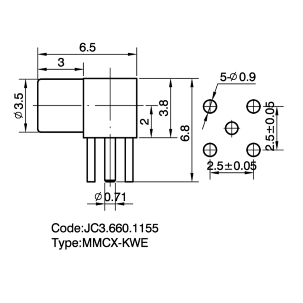
MMCX PCB Connectors Custom

Home / Products / Coaxial Connectors / MMCX RF Coaxial Connectors / MMCX PCB Connectors

MMCX PCB Connectors Manufacturer

Product Introduction:
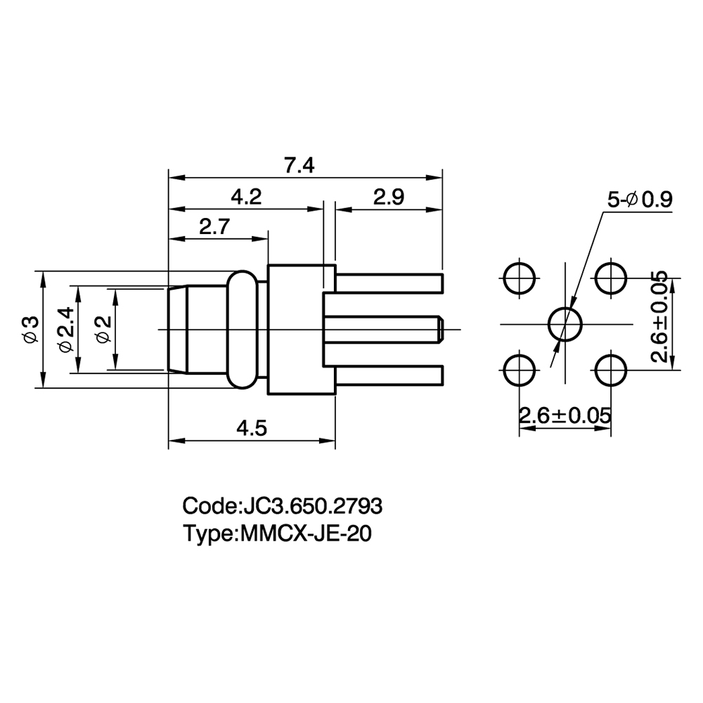
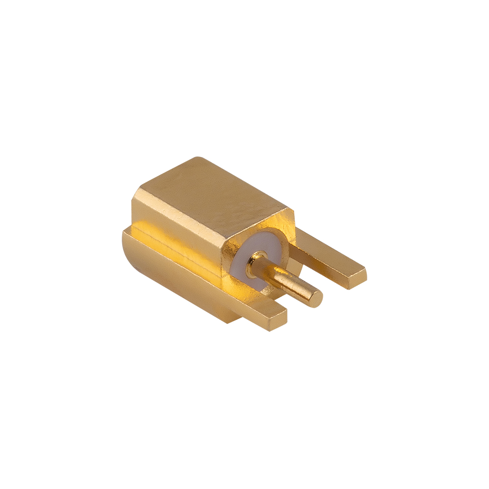
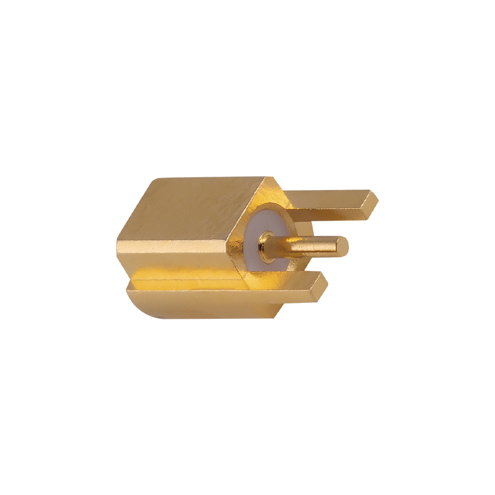
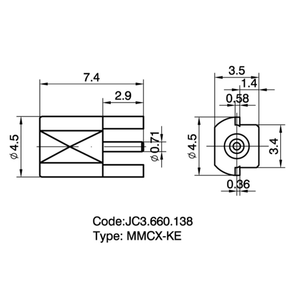
Provides multiple PCB mounting options, including straight, right-angle, and edge-mount types.

Product Features:
Ultra-low insertion loss design: The center pin uses a thick gold-plating process, significantly reducing contact resistance.
Board-edge optimization: The edge-mount connector is specifically designed for thin PCBs, allowing seamless edge integration and reducing vertical height.
Excellent thermal performance: High-performance PTFE insulating material maintains stable impedance even under long-term high-power transmission.

Application Advantages:
High-density PCB layout: More RF interfaces can be arranged within a 10 mm² area, serving as a key component for implementing MIMO (Multiple Input Multiple Output) technology.
Reduced production cost: Standardized pin design is compatible with mainstream PCB layouts and supports reflow soldering, improving yield in mass production.

Temperature Range

-55~+155℃(PE Cable   -40~+85℃)

Impedance

50Ω

Frequency Range

DC~6GHz

Insulation resistance

≥1000MΩ

Insertion loss

0.18 dB/1GHz

Voltage Standing Wave Ratio (VSWR)

Straight ≤1.25/3GHz


Right angle ≤1.43/3GHz

 Durability(mating)

≥500 cycles

About
Yangzhou Jingcheng Electronics Co., Ltd.

Yangzhou Jingcheng Electronics Co., Ltd., a premier China MMCX PCB Connectors Manufacturer and MMCX PCB Connectors Supplier, was founded in 1999. It is a high-tech enterprise specializing in the R&D and manufacturing of RF coaxial connectors, cable assemblies, and passive microwave components.
Equipped with a comprehensive R&D and production system, the company has obtained international certifications including ISO9001. Adhering strictly to standards such as MIL, IEC and GB, we offer over 30 product series with more than 2,000 specifications, covering SMA, BNC, N-type and other mainstream models. Our products are widely applied in the fields of communications, aerospace, automotive electronics and beyond, and exported to many countries and regions across Europe, America and Asia.
We uphold the tenet of "Quality as the Foundation, Customers as the Core", committed to providing reliable interconnection solutions and professional services for global clients.

MMCX PCB Connectors Industry knowledge

Category Overview

MMCX PCB Connectors are micro-miniature radio frequency coaxial connectors designed for direct printed circuit board mounting. They adhere to the MMCX interface standard, featuring a snap-on coupling mechanism that enables quick connect and disconnect while maintaining a 50-ohm impedance. The connector's outer diameter of approximately 2.4 mm makes it one of the smallest RF connector solutions available for PCB integration, allowing high-density layouts in space-constrained wireless devices. Typical frequency range spans from DC to 6 GHz, with high-performance variants extending to 12 GHz, making these connectors suitable for a wide range of RF and microwave applications.

Yangzhou Jingcheng Electronics (JC), founded in 1999, manufactures MMCX PCB Connectors as part of its extensive RF coaxial connector portfolio. The company's production capability for these connectors is supported by advanced manufacturing equipment, precision testing facilities, and a strong technical team. Each MMCX PCB connector undergoes rigorous dimensional and electrical verification to ensure reliable signal transmission and consistent impedance matching across the specified frequency band. The snap-on mating design provides audible and tactile feedback upon proper engagement, and the mated pair allows 360-degree rotation, simplifying cable routing within compact electronic enclosures.

MMCX PCB Connectors are widely deployed in wireless communication modules, GPS/GNSS receivers, Bluetooth devices, IoT endpoints, portable test instruments, and automotive telematics. Their miniature footprint, compared to larger connectors such as MCX or SMA, enables significant board space savings without compromising electrical performance. The availability of various PCB mounting orientations—vertical, right-angle, surface-mount, and edge-launch—provides design flexibility for diverse enclosure geometries and antenna port positions.

Common Types & Characteristics

Mounting Type PCB Orientation Termination Method Key Characteristics
PCB Vertical Mount Straight / Vertical Through-hole soldering Mating axis perpendicular to PCB plane; robust mechanical anchoring via through-hole legs; suitable for top-panel antenna connections.
PCB Right-Angle Mount Right-Angle / Horizontal Through-hole soldering Mating axis parallel to PCB surface; ideal for edge-panel configurations; reduces overall enclosure height profile.
SMT (Surface-Mount) Straight or Right-Angle Surface-mount reflow soldering Compatible with automated pick-and-place assembly; requires precise pad layout; suitable for high-volume production; may incorporate reinforced ground pads for mechanical stability.
Edge-Mount / End-Launch Edge-aligned Soldering to PCB edge pads Positioned at PCB perimeter for direct external access; minimizes signal path length; often used in modules requiring panel-mount antenna connections without cabling.
Bulkhead / Panel Mount Panel-fixed Cable connection to PCB Mounted through enclosure wall with locking nut; connector accessible externally; internal connection via flexible cable assembly to the main PCB.

Comparative Analysis: MMCX PCB Connectors vs. Related Interface Types

3.1 MMCX PCB Connector vs. MMCX Switch Socket

Feature MMCX PCB Connector MMCX RF Coaxial Switch Socket
Switching Function No internal switch Integrated mechanical switch (NC default)
Signal Paths Single fixed path Two selectable paths
Typical Use Case Direct antenna or cable connection Internal/external antenna switching
Insertion Loss (typical at 6 GHz) ≤ 0.2 dB ≤ 0.3 dB (switch path)
Frequency Range DC to 6 GHz (up to 12 GHz) DC to 6 GHz (up to 12 GHz)

3.2 MMCX vs. MCX vs. SMA PCB Connectors

Parameter MMCX PCB Connector MCX PCB Connector SMA PCB Connector
Outer Diameter (approx.) ~2.4 mm ~3.6 mm ~6.35 mm (1/4 inch)
Coupling Type Snap-on (quick connect/disconnect) Snap-on Threaded screw coupling
Frequency Range DC to 6 GHz (extended to 12 GHz) DC to 6 GHz DC to 18 GHz (or higher)
Board Footprint Smallest among the three Medium Largest
Durability (Mating Cycles) Typically 500 cycles Typically 500 cycles Typically 500+ cycles
Typical Application Portable devices, IoT, high-density PCBs GPS, automotive, consumer wireless Test equipment, base stations, lab use

Application Scenarios

MMCX PCB Connectors are utilized across industries where compact size, reliable RF performance, and ease of mating are essential design requirements. Their ability to support frequencies up to 6 GHz and beyond makes them suitable for numerous wireless applications. Common deployment scenarios include:

• Wireless Communication Modules

Integrated into Wi-Fi, cellular, and LoRa modules as the primary antenna interface, enabling direct connection to external antennas or test equipment.

• GPS / GNSS Receivers

Provides a compact antenna connection point for GPS modules in vehicle tracking, surveying equipment, and asset tracking devices.

• Bluetooth & IoT Devices

Enables antenna connectivity in Bluetooth headsets, wearable sensors, smart home devices, and industrial IoT endpoints where board space is limited.

• Handheld Test & Measurement

Used as a test port in portable spectrum analyzers, signal generators, and field measurement instruments for convenient cable connection.

• Automotive Telematics

Employed in OBD dongles, telematics control units, and vehicle-to-everything communication modules for external antenna interfacing.

• Medical Wireless Devices

Supports antenna connections in wireless patient monitors, medical implants, and diagnostic equipment where miniaturization is critical.

Selection Guide & Key Considerations

Selecting the appropriate MMCX PCB connector for a specific design requires evaluation of several technical parameters. Yangzhou Jingcheng Electronics offers a broad range of MMCX connector configurations and can provide technical support to assist design engineers in component selection. The following criteria should be considered during the selection process:

Selection Criterion Description Guidance
Operating Frequency The frequency band over which the connector must maintain specified VSWR and insertion loss. Select a connector rated for the target frequency range. Standard MMCX connectors cover DC to 6 GHz; extended-range types reach 12 GHz.
PCB Mounting Configuration The physical orientation and soldering method on the PCB. Choose vertical, right-angle, SMT, or edge-mount based on enclosure design and antenna port location. Consider assembly process compatibility (reflow vs. wave soldering).
Impedance Characteristic impedance of the transmission path. Standard is 50 ohms, matching most RF systems. Confirm system impedance to avoid mismatch losses.
VSWR / Return Loss Measure of impedance matching quality across the frequency band. Review VSWR specifications—typical values are ≤ 1.3:1 at 6 GHz. Lower VSWR indicates better matching and less signal reflection.
Insertion Loss Signal attenuation introduced by the connector. Typical insertion loss is ≤ 0.2 dB at 6 GHz for a mated pair. Evaluate at the highest operating frequency for link budget calculations.
Mating Cycle Durability Number of connect/disconnect operations before performance degrades. Standard rating is 500 cycles minimum. For applications requiring frequent mating, consult durability specifications.
Environmental Conditions Temperature range, humidity, and other ambient factors. MMCX PCB connectors typically operate from -40°C to +85°C. For extended temperature ranges, verify with manufacturer specifications.

Frequently Asked Questions

Q1: What is an MMCX PCB Connector?

An MMCX PCB Connector is a micro-miniature 50-ohm RF coaxial connector designed for direct soldering onto a printed circuit board. It features a snap-on coupling mechanism that allows quick and secure mating without the need for threading tools. Its compact size—with an outer diameter of approximately 2.4 mm—enables high-density PCB layouts in wireless devices.

Q2: What is the difference between MMCX and MCX PCB connectors?

The primary difference lies in the physical size. MMCX connectors are approximately 30% smaller than MCX connectors, with an outer diameter of about 2.4 mm compared to MCX's 3.6 mm. Both use a snap-on coupling mechanism and support similar frequency ranges (DC to 6 GHz), but MMCX is preferred when board space is extremely limited. The two interfaces are not intermateable.

Q3: Can MMCX PCB connectors be used in automated assembly?

Yes. Surface-mount (SMT) MMCX connectors are specifically designed for automated pick-and-place equipment and reflow soldering processes. Through-hole versions can be processed using wave soldering or selective soldering. Yangzhou Jingcheng Electronics provides recommended PCB footprint layouts and soldering profiles for its MMCX connector products to facilitate automated assembly.

Q4: What frequency range do MMCX PCB connectors support?

Standard MMCX PCB connectors operate effectively from DC to 6 GHz. Extended-performance designs can reach up to 12 GHz. The actual usable frequency depends on the connector design, materials, and PCB transition. JC utilizes precision testing equipment to verify performance across these frequency bands.

Q5: What materials are used in MMCX PCB connectors?

The body and center contact are typically manufactured from brass or beryllium copper, with gold plating over a nickel underplate to ensure corrosion resistance and reliable electrical contact. Insulators are made from PTFE or other low-loss dielectric materials. The specific material selection influences contact resistance, durability, and frequency performance.

Q6: How many mating cycles can an MMCX PCB connector withstand?

The standard durability rating for MMCX connectors is 500 mating cycles minimum, after which electrical parameters such as contact resistance and VSWR should remain within the specified limits. Actual cycle life may vary based on insertion technique and environmental conditions. For applications with higher cycle requirements, JC can provide guidance on suitable product variants.

Technical Notes

  • The snap-on interface of MMCX connectors provides audible and tactile feedback upon proper mating, reducing the risk of partial connections that could cause signal degradation.
  • After mating, the connector pair permits 360-degree rotation without affecting electrical performance, which assists in cable management within compact enclosures.
  • PCB layout for MMCX connectors should employ controlled-impedance transmission line structures (such as grounded coplanar waveguide or microstrip) to maintain 50-ohm impedance from the IC to the connector pad.
  • Proper grounding of the connector body to the PCB ground plane is essential for consistent electrical performance and minimizing parasitic effects at higher frequencies.
  • Yangzhou Jingcheng Electronics, with manufacturing experience since 1999, maintains in-house testing capabilities for RF connectors including VSWR, insertion loss, and isolation measurements from DC to 50 GHz, ensuring each product meets the required specifications.