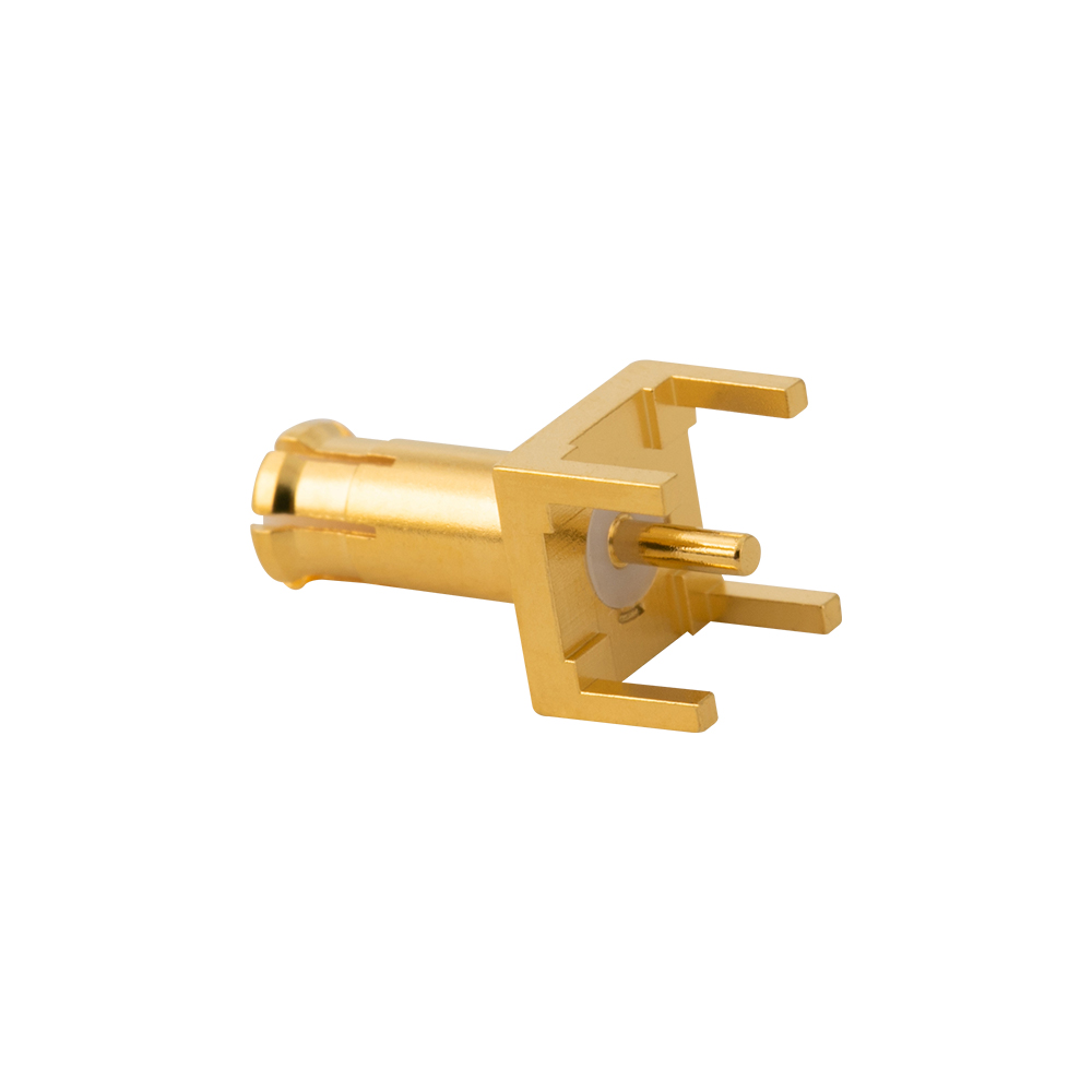
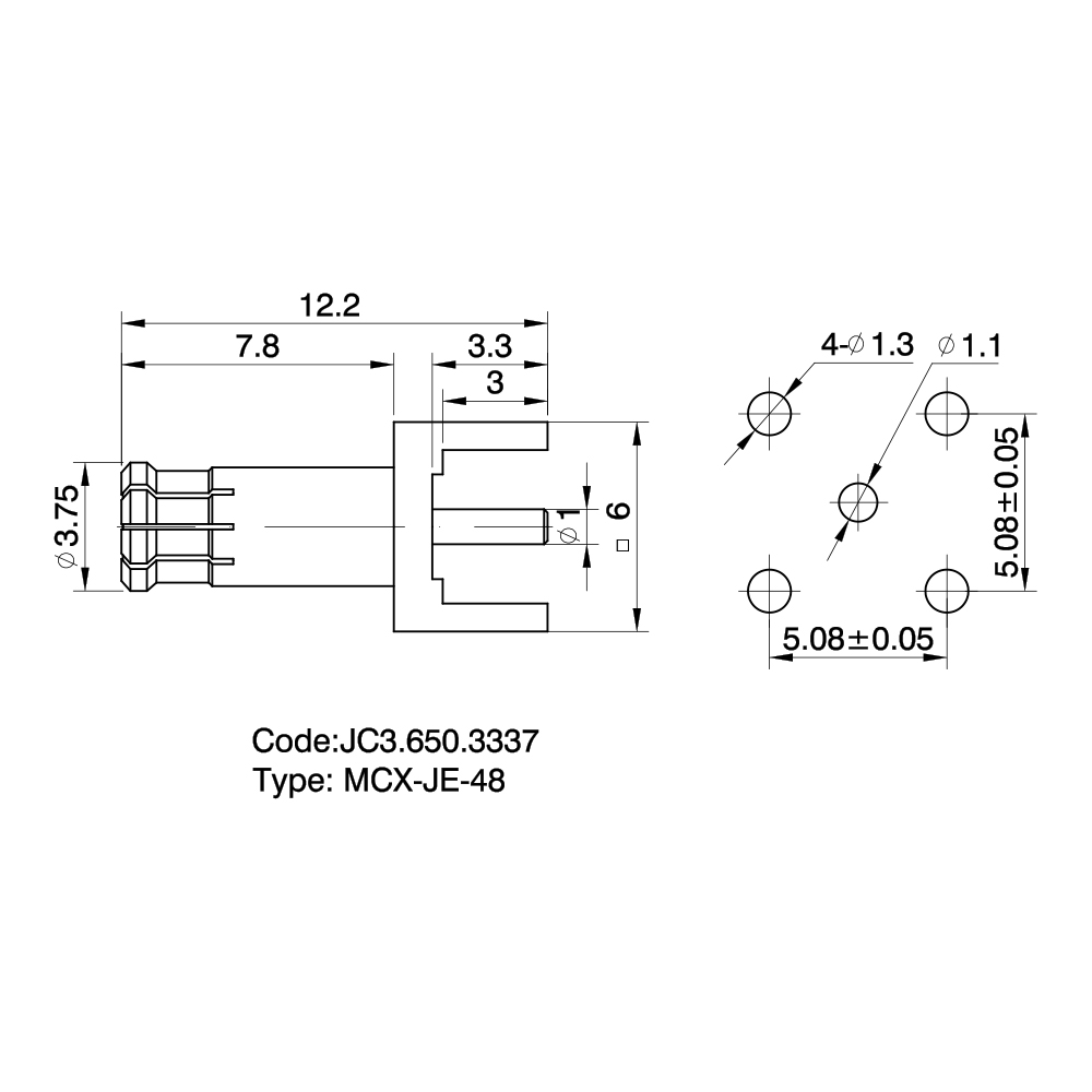
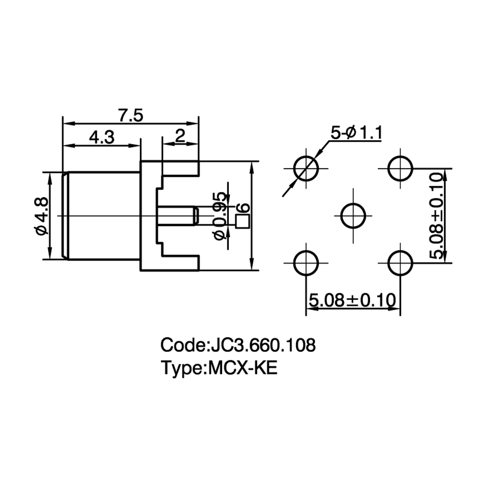
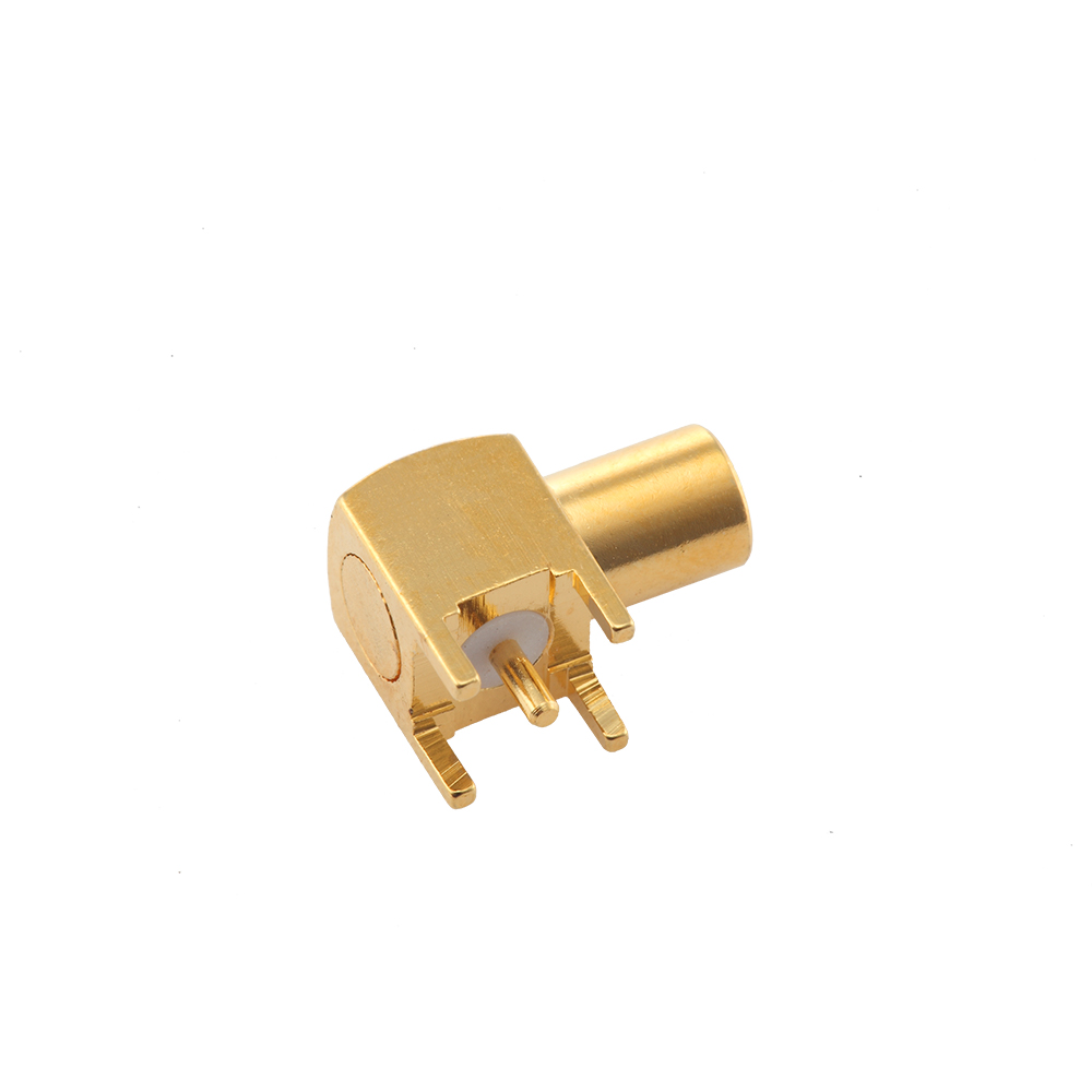
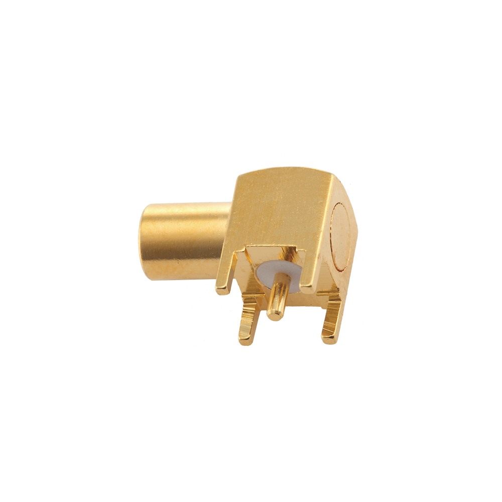
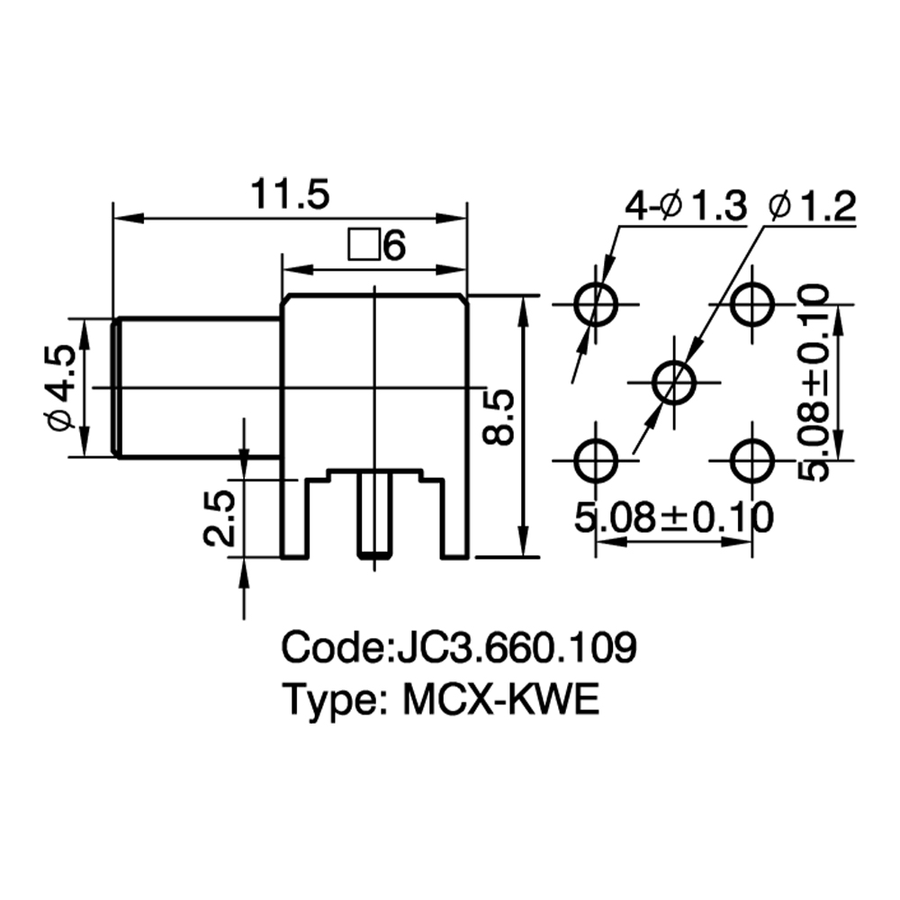
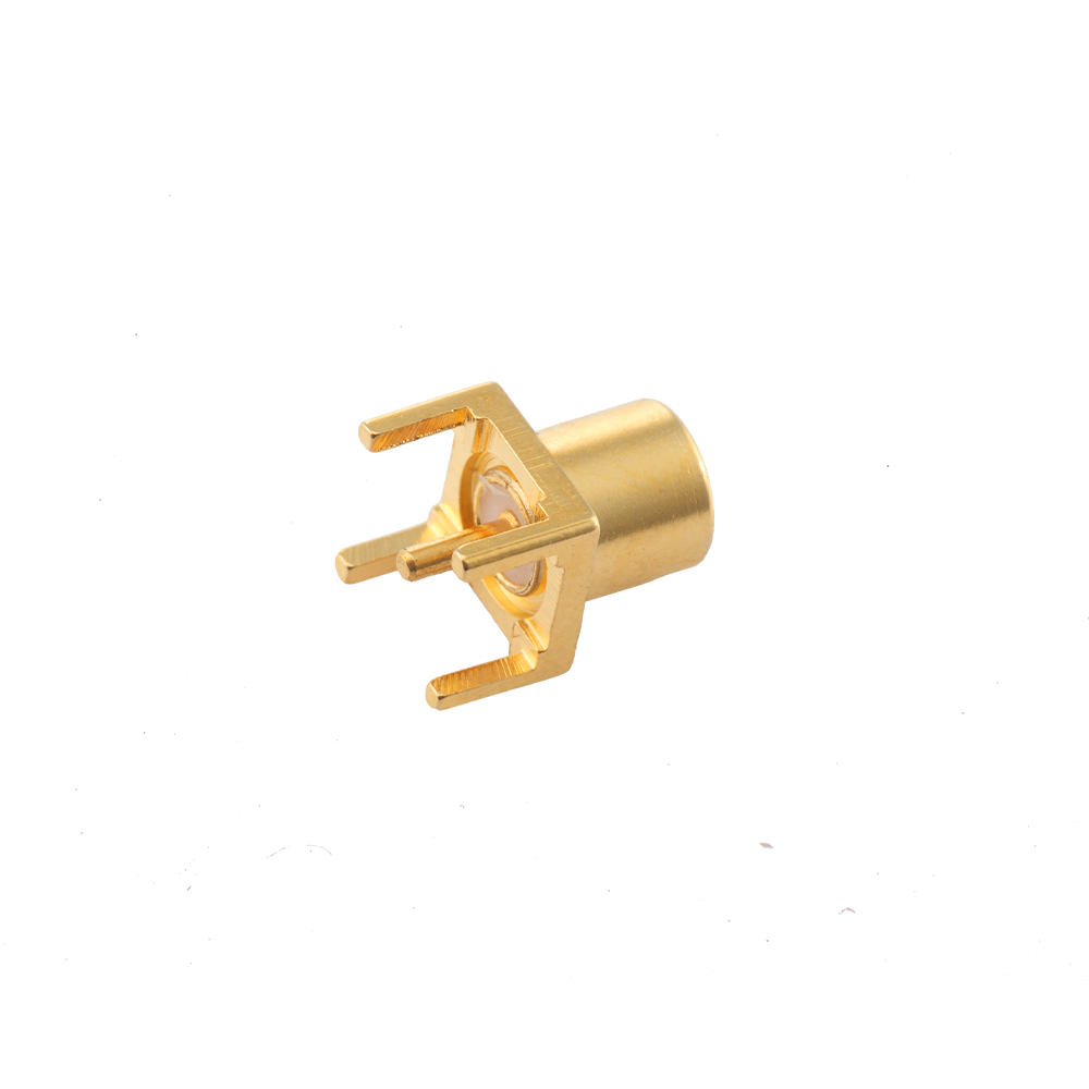
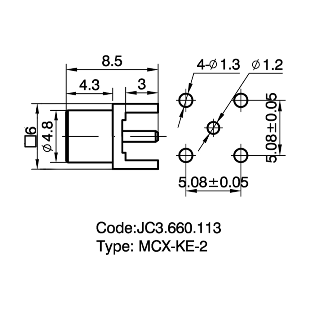
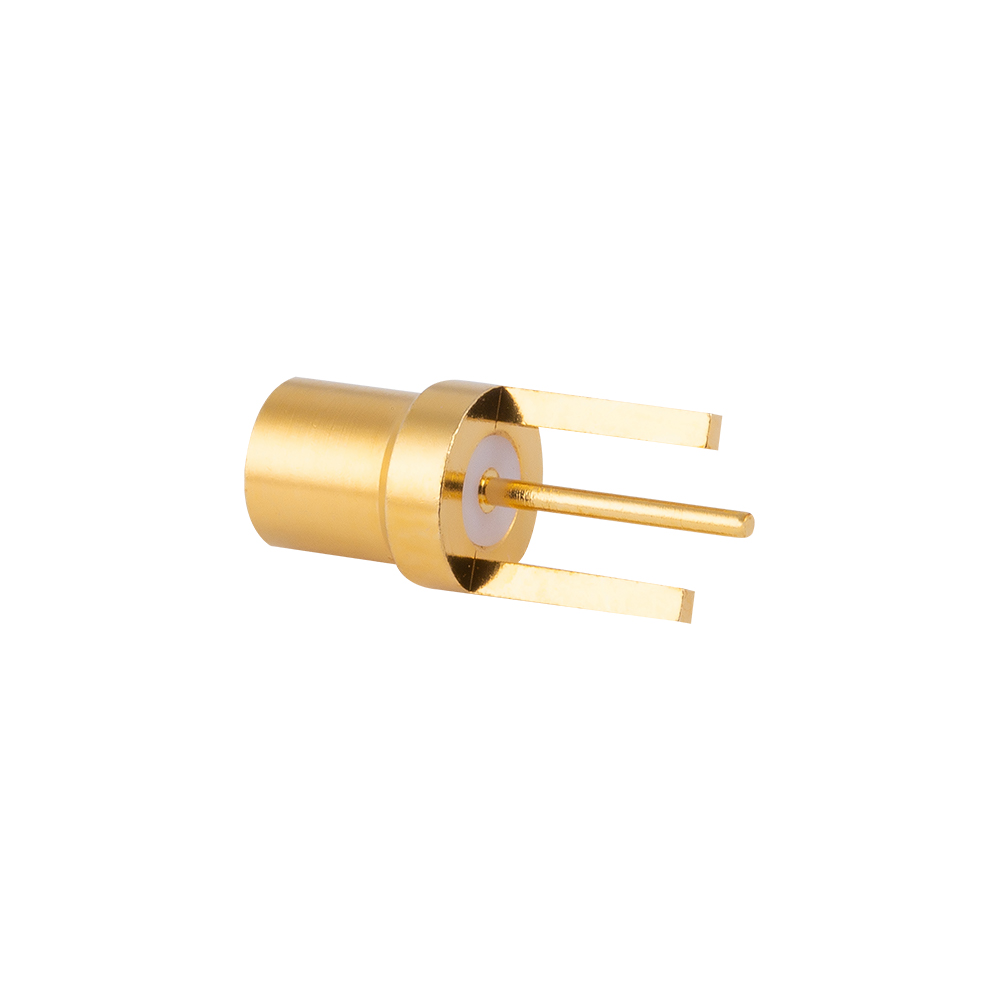
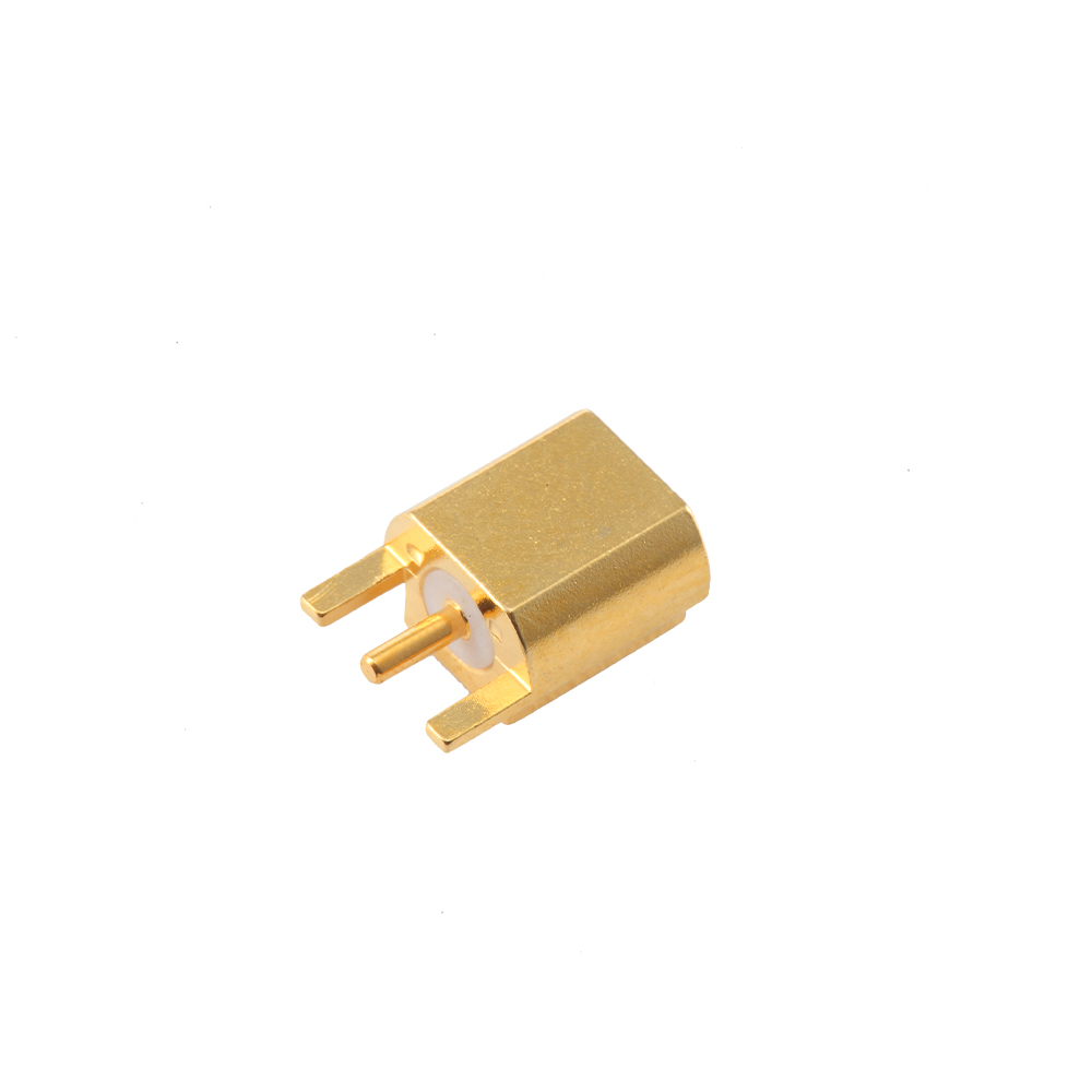
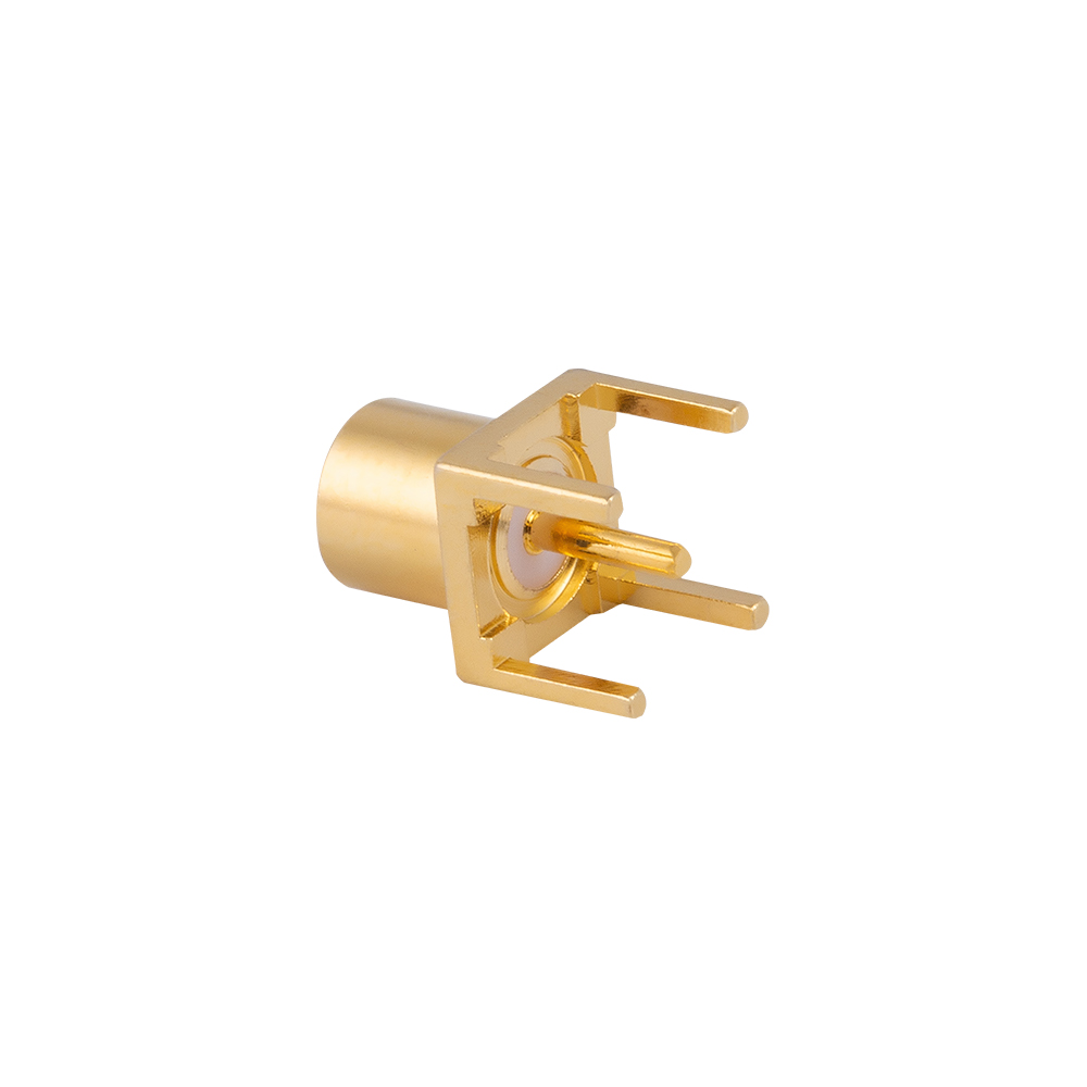
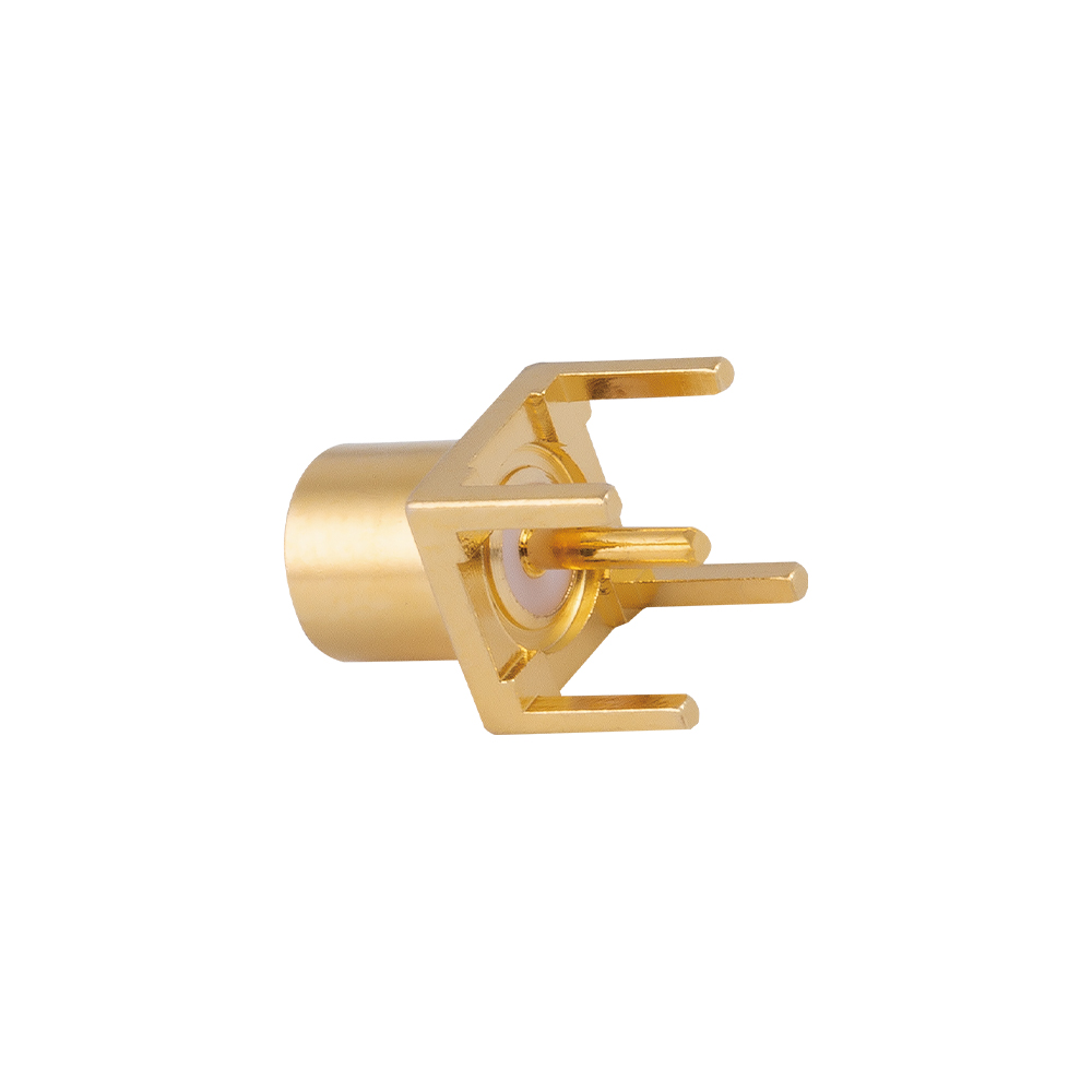
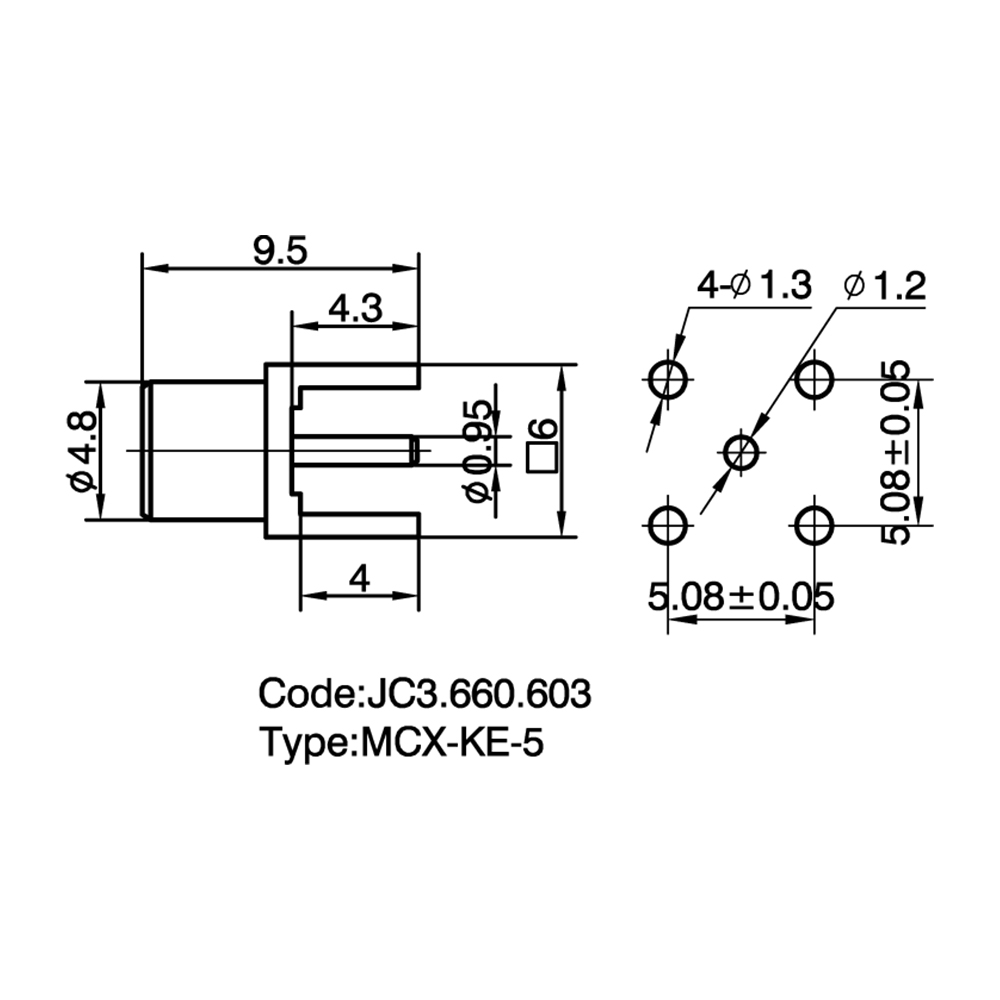
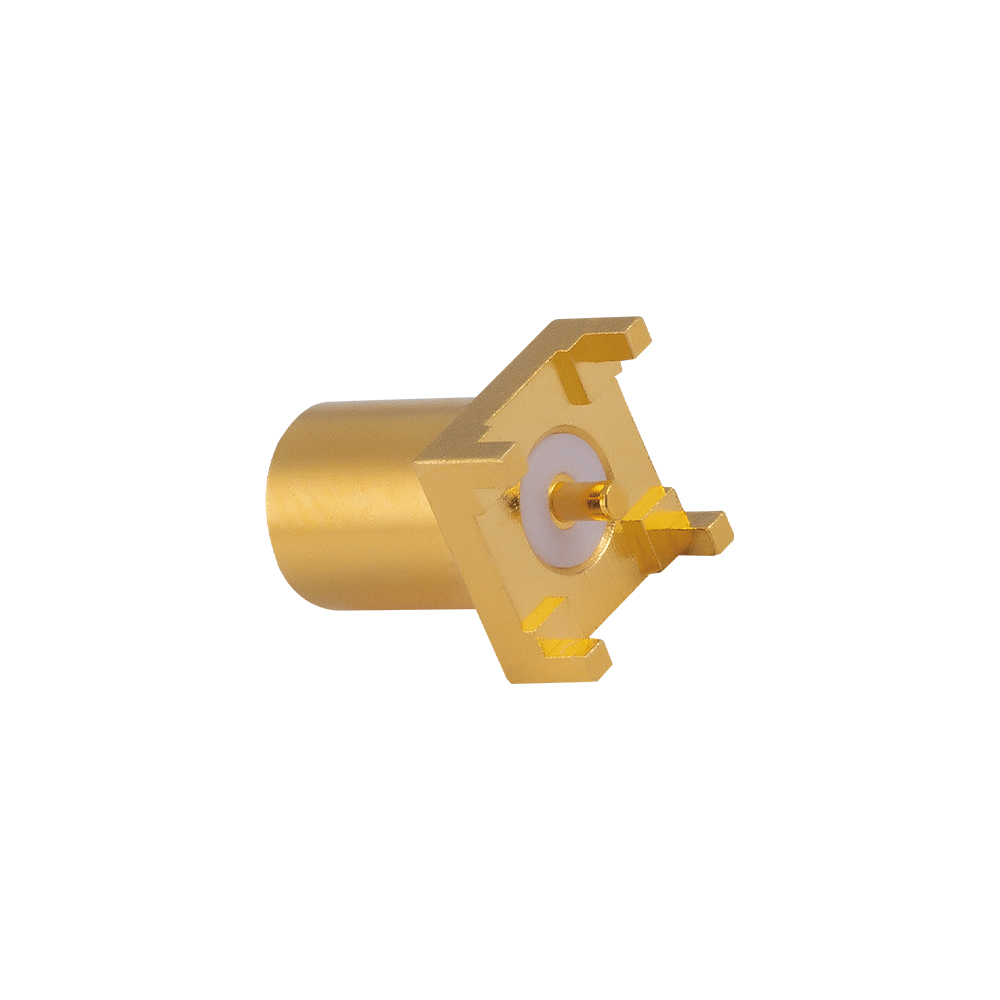
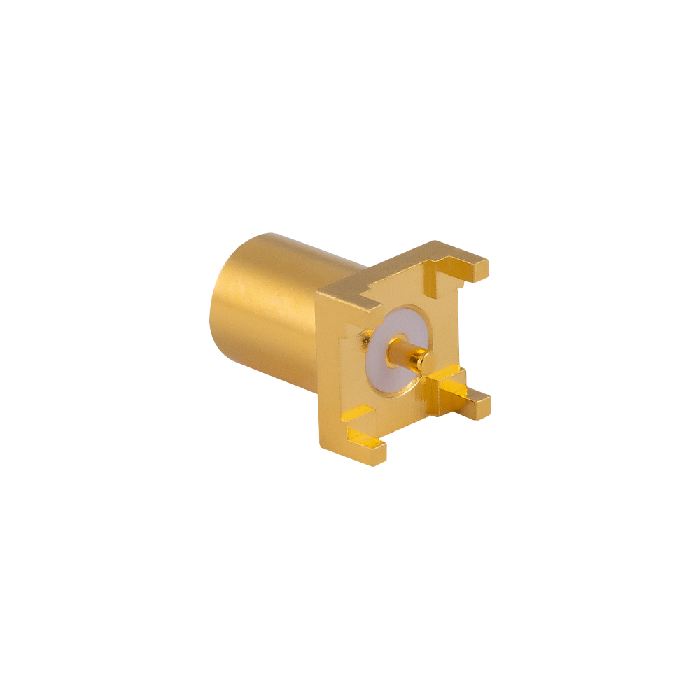
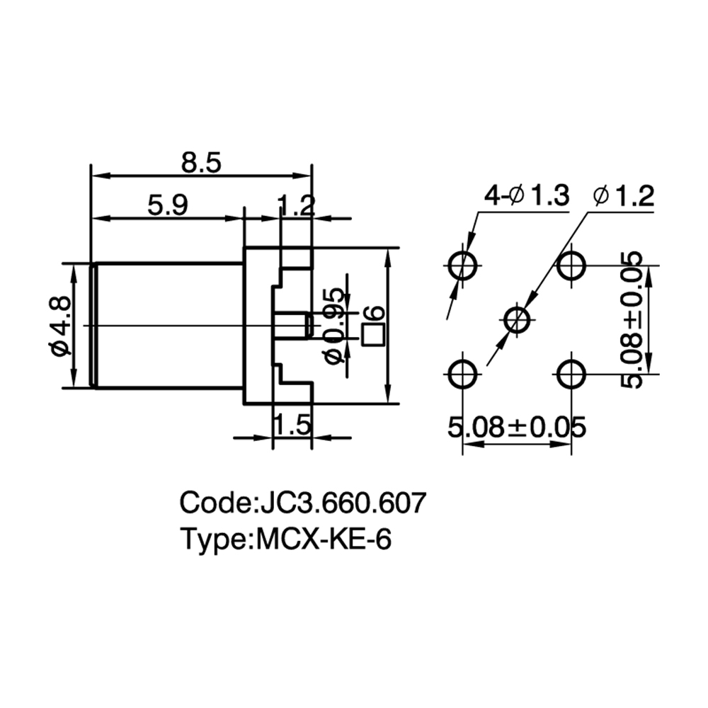
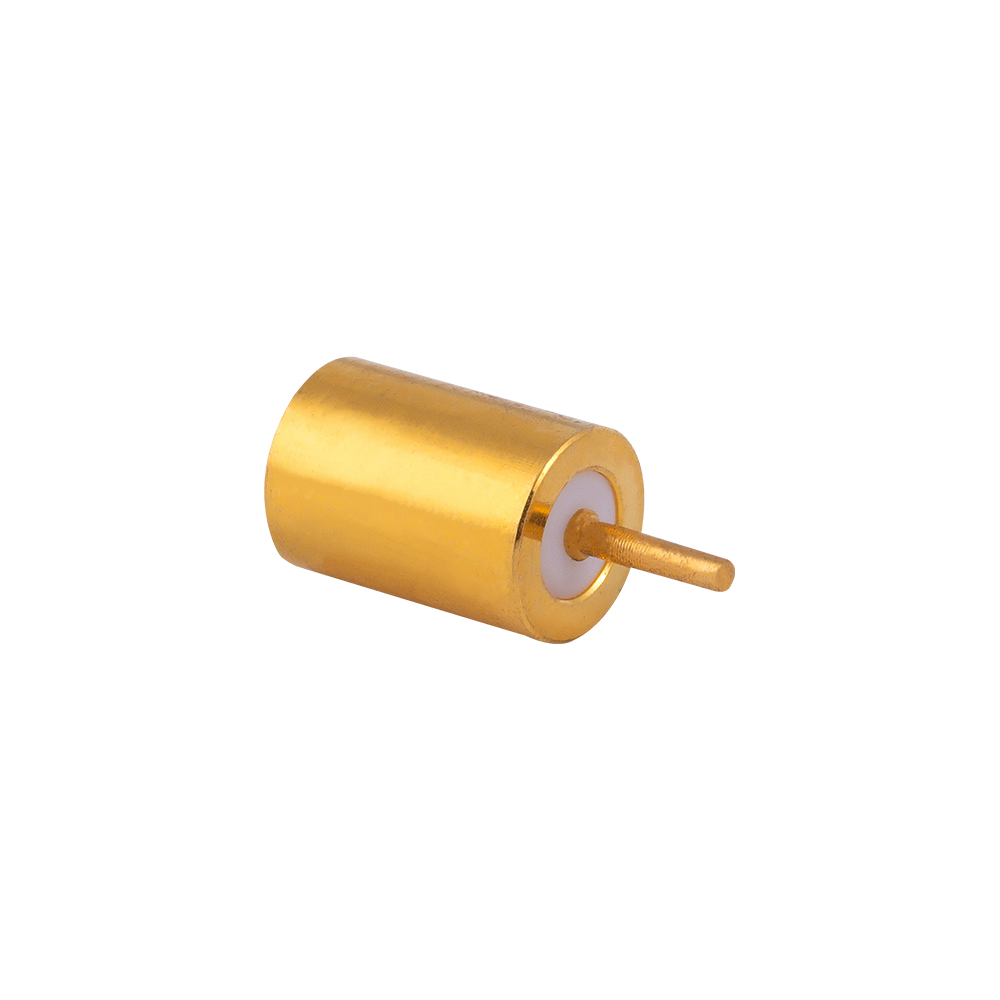
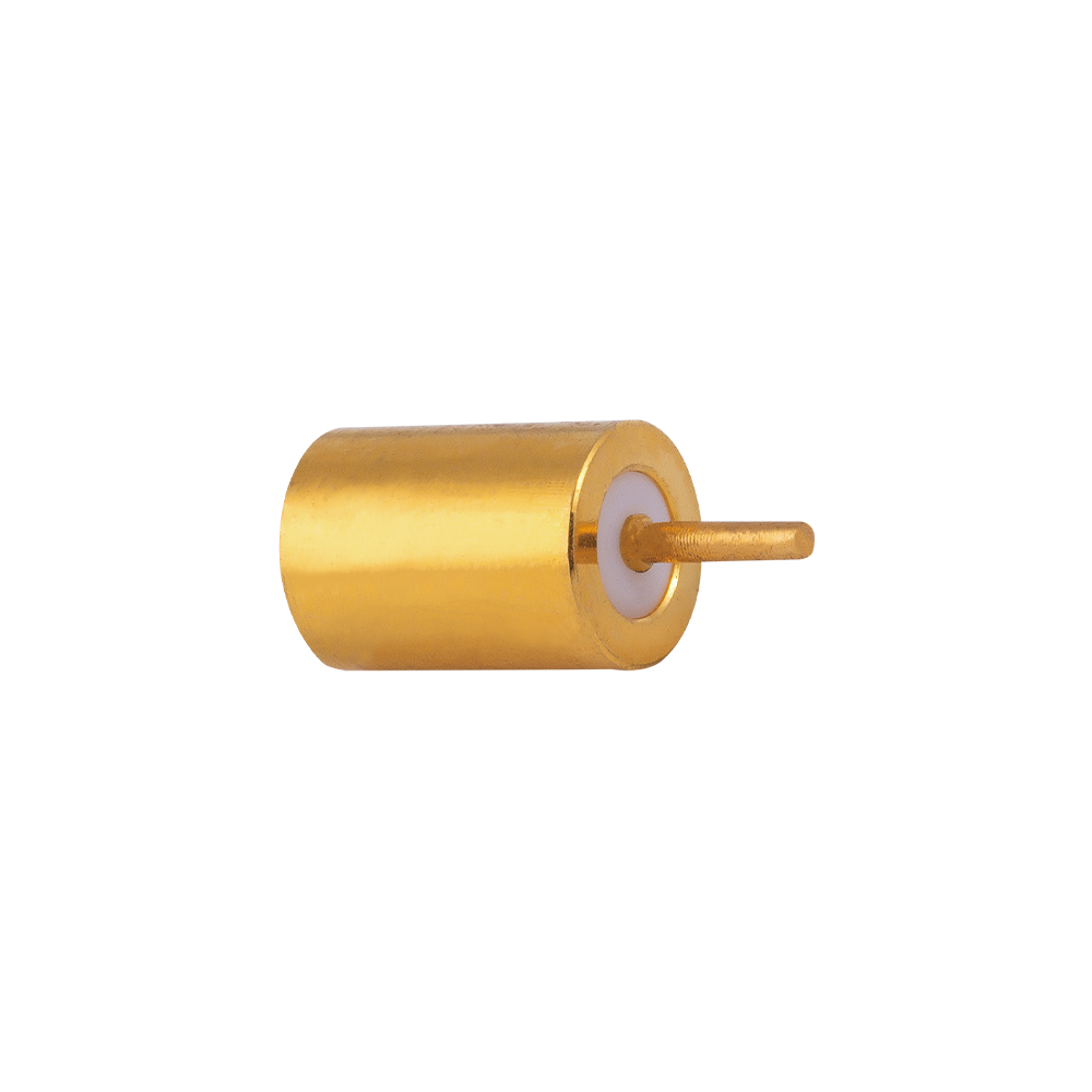
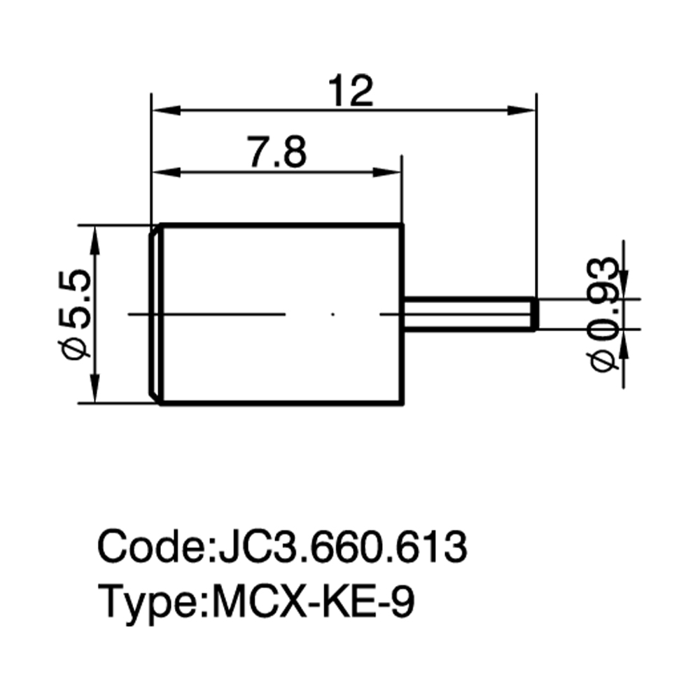
MCX PCB Mount Connectors are micro-miniature coaxial interfaces designed for secure RF connections through a snap-on coupling mechanism. These connectors operate reliably up to 6 GHz and feature a characteristic impedance of 50 ohms. The primary function of the PCB mount configuration is to provide a direct and stable transition from a coaxial cable to a printed circuit board trace, minimizing signal loss in compact electronic assemblies. Yangzhou Jingcheng Electronics Co., Ltd. supplies a comprehensive range of MCX PCB solutions that facilitate efficient board-level integration across various wireless systems.
Common Types and Characteristics
The MCX PCB mount series is categorized by mounting configuration to accommodate different PCB layouts and mechanical constraints. Below are the standard types available:
| Type |
Key Characteristics |
Typical Interface Feature |
| Straight Through-hole Jack |
Vertical orientation, robust mechanical fixation. Features standard solder legs for reliable plating through-hole (PTH) connection. |
Snap-on female socket, standard PCB footprint. |
| Right-angle Through-hole Jack |
Horizontal orientation for low-profile designs. Saves vertical space within the enclosure. |
90-degree snap-on interface, dip solder terminals. |
| Edge-mount Jack |
Designed to mount on the edge of the PCB. Allows for peripheral connections and simplifies enclosure design. |
Snap-on interface aligned parallel to the board surface. |
| Surface-mount (SMT) Jack |
Packaged for automated pick-and-place assembly. Compatible with standard reflow soldering processes. |
Planar leads or gull-wing leads, tape-and-reel packaging available. |
Application Scenarios
The compact dimensions and reliable snap-on coupling make these connectors suitable for high-density RF modules. Typical applications include:
- Telecommunications: Base station infrastructure, repeaters, and small cells.
- GNSS/GPS Modules: Navigation and positioning antenna interfaces.
- Wireless LAN: Wi-Fi access points and routers requiring internal antenna connections.
- Test and Measurement: Portable spectrum analyzers and field test equipment where quick connect/disconnect is essential.
- Digital Broadcasting: DVB-T receivers and similar digital TV peripherals, an area where Yangzhou Jingcheng Electronics Co., Ltd. has extensive application experience.
Selection Guide
Choosing the correct MCX PCB connector requires evaluating mechanical and electrical parameters:
- Orientation vs. Space: Select straight configurations for top-access testing, right-angle for slim-profile enclosures, and edge-mount for peripheral board access.
- Assembly Process: Choose through-hole types for hand-soldering or enhanced vibration resistance. Select surface-mount (SMT) types for high-volume, automated production.
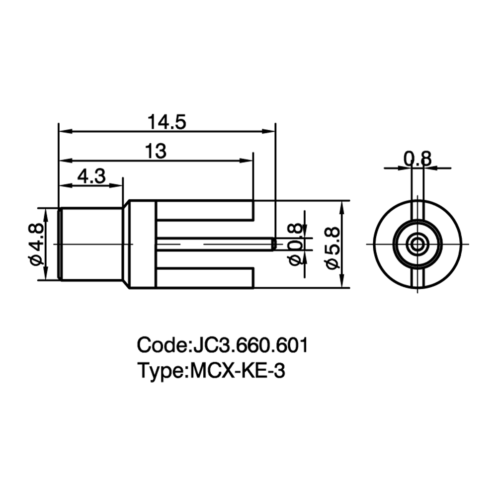
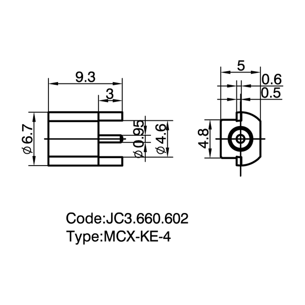
- Board Layout: Verify the PCB footprint pad layout against the connector datasheet to ensure proper ground plane contact and impedance matching (50 Ohm).
- Plating and Materials: Check contact plating, such as gold over nickel, for corrosion resistance and consistent electrical conductivity over time. Body material typically includes brass with nickel plating.
Comparative Analysis: MCX vs. MMCX vs. SMB
| Feature |
MCX |
MMCX |
SMB |
| Size |
Micro-miniature |
Ultra-miniature (Smaller than MCX) |
Sub-miniature (Larger than MCX) |
| Coupling |
Snap-on |
Snap-on (Allows 360° rotation) |
Snap-on |
| Frequency Range |
DC to 6 GHz |
DC to 6 GHz |
DC to 4 GHz |
| Primary Compatibility |
Not directly interchangeable with MMCX or SMB. |
Compatible with MCX only with specific adapters. |
Not compatible with MCX without an adapter. |
Frequently Asked Questions (FAQ)
Q: What are the main advantages of MCX connectors compared to other RF interfaces?
A: The primary advantage is the compact physical footprint combined with the rapid snap-on coupling. They provide a tool-less mating solution that reduces installation time while maintaining stable electrical performance up to 6 GHz, a balance often required in dense RF modules.
Q: Are MCX connectors compatible with MMCX connectors?
A: No, standard MCX and MMCX interfaces do not directly mate. While both use a snap-on mechanism and share similar 50-ohm impedance, the physical dimensions and detent mechanisms differ. Forcing a mismatched connection can damage the center contacts or dielectric insulators.
Q: Can I obtain specific PCB layout footprints for these connectors from your company?
A: Yes, recommended PCB layout files and technical drawings are provided by Yangzhou Jingcheng Electronics Co., Ltd. to ensure correct signal trace routing and ground plane clearance. Matching the footprint precisely is critical to maintaining the 50-ohm impedance profile and mechanical stability.
Q: What testing standards are applied to these MCX PCB connectors?
A: Standard production testing typically covers Voltage Standing Wave Ratio (VSWR), insertion loss, and insulation resistance. High-precision testing equipment is used during manufacturing to validate that connectors meet specified electrical and mechanical parameters.


 English
 中文简体
中文简体