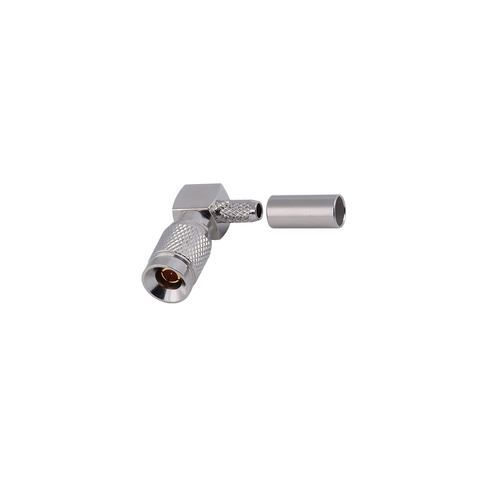
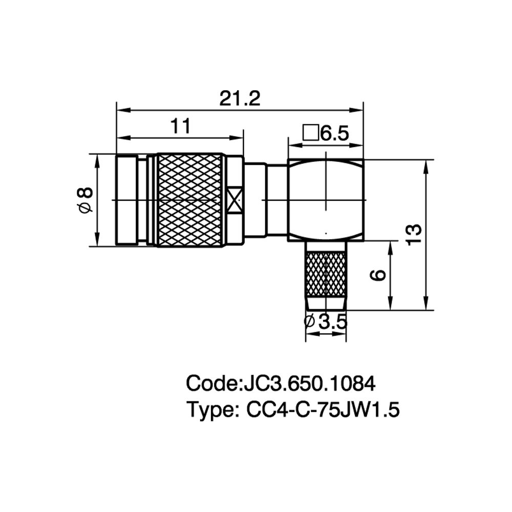
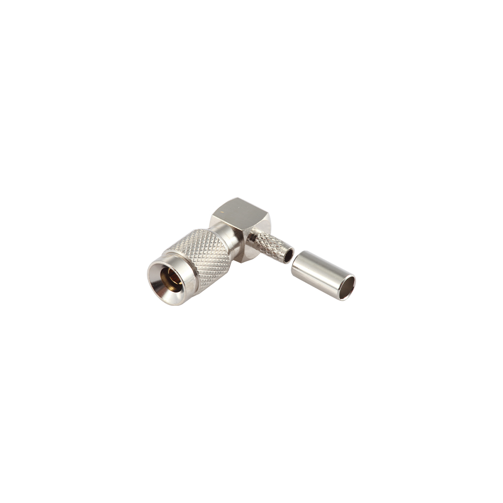
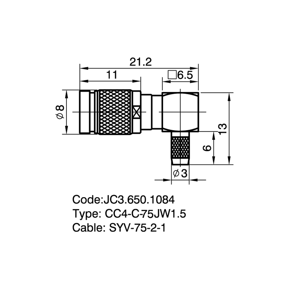
1.0/2.3(CC4) Connectors for flexible cable Custom

Home / Products / Coaxial Connectors / 1.0/2.3(CC4) RF Coaxial Connectors / 1.0/2.3(CC4) Connectors for flexible cable

1.0/2.3(CC4) Connectors for flexible cable Manufacturer

Product Overview
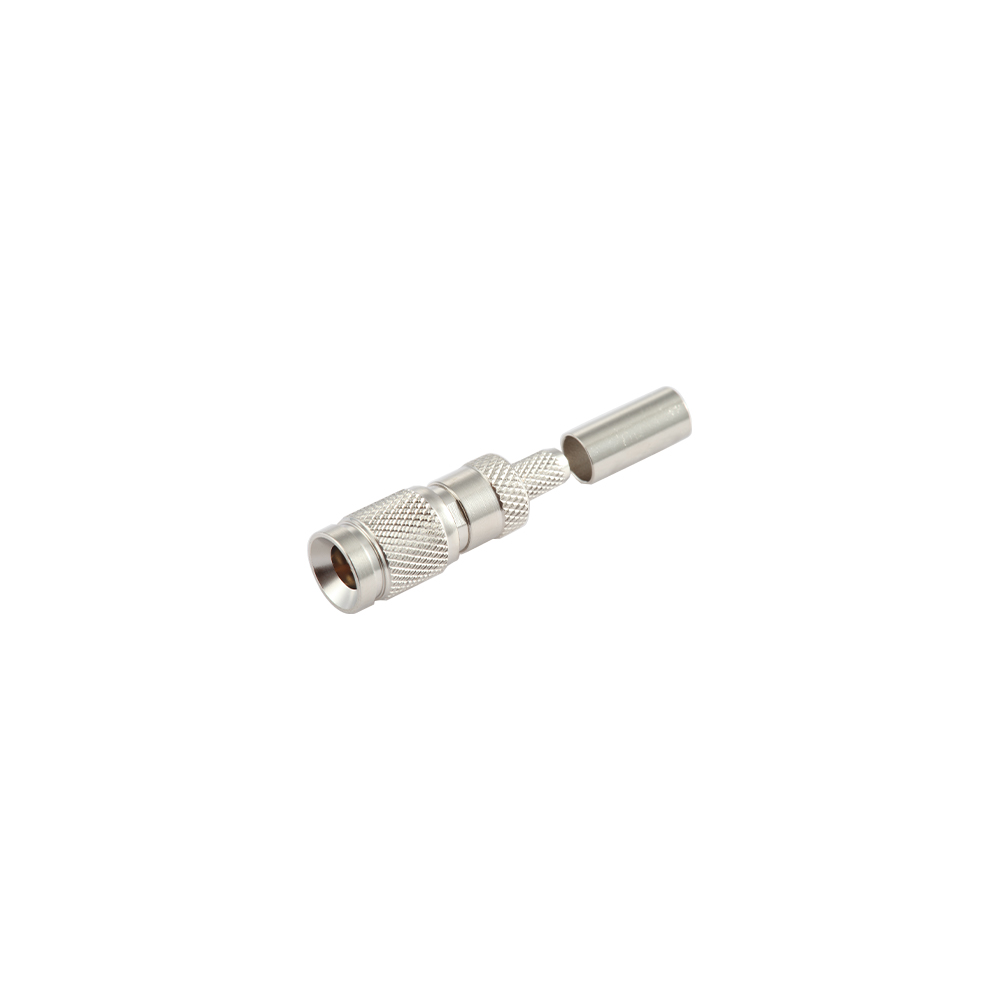
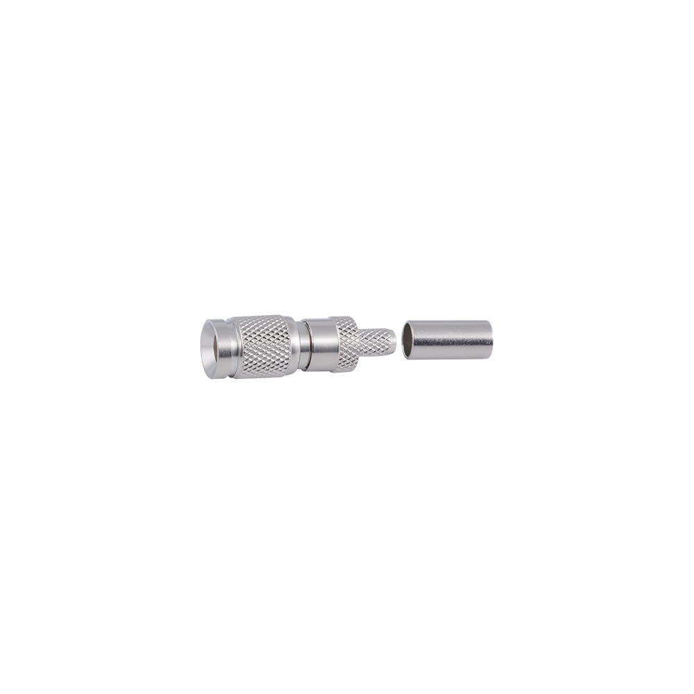
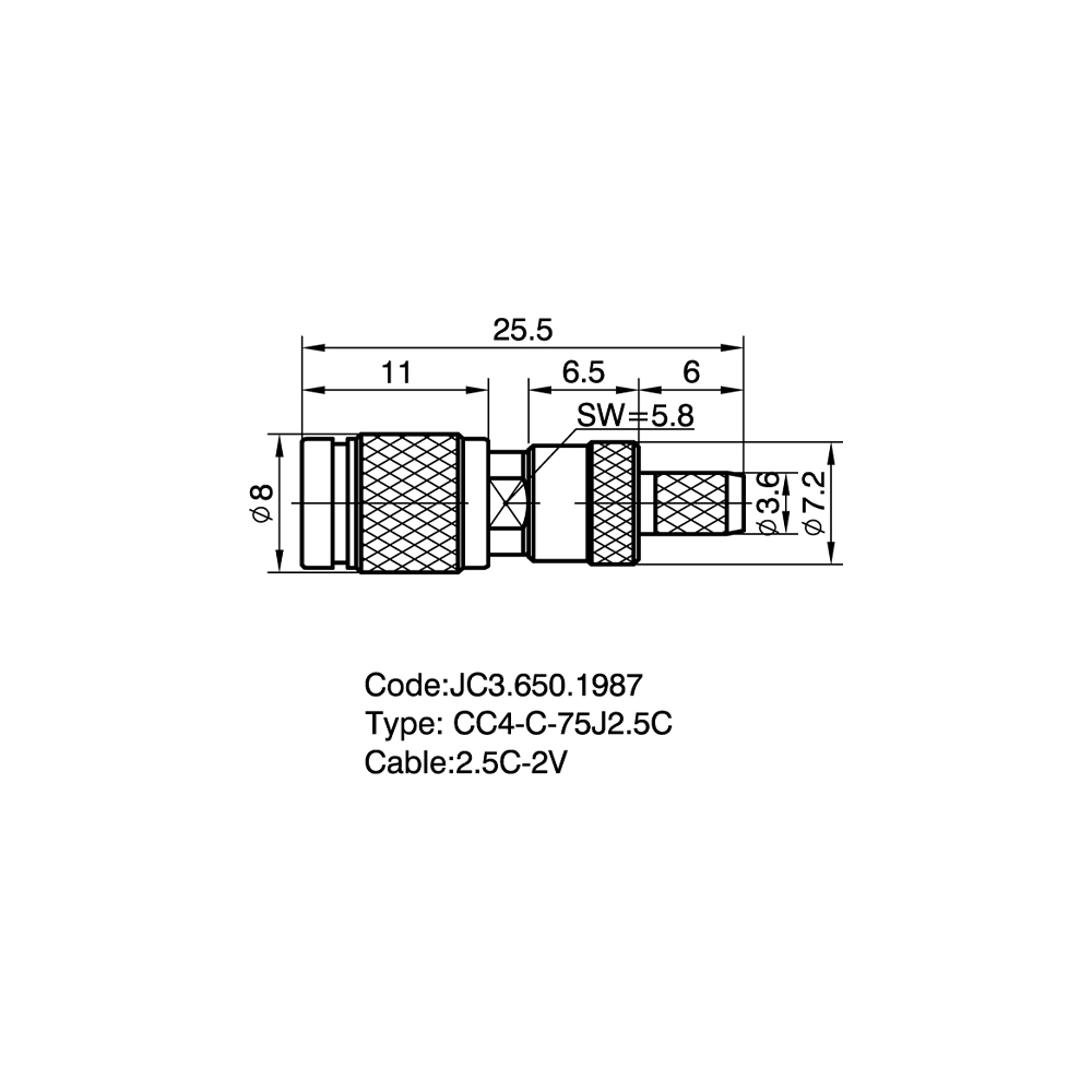
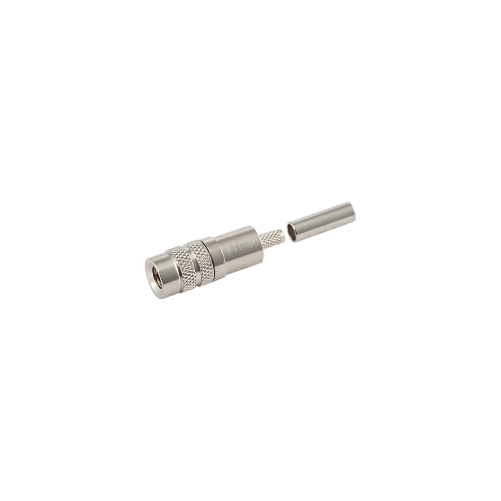
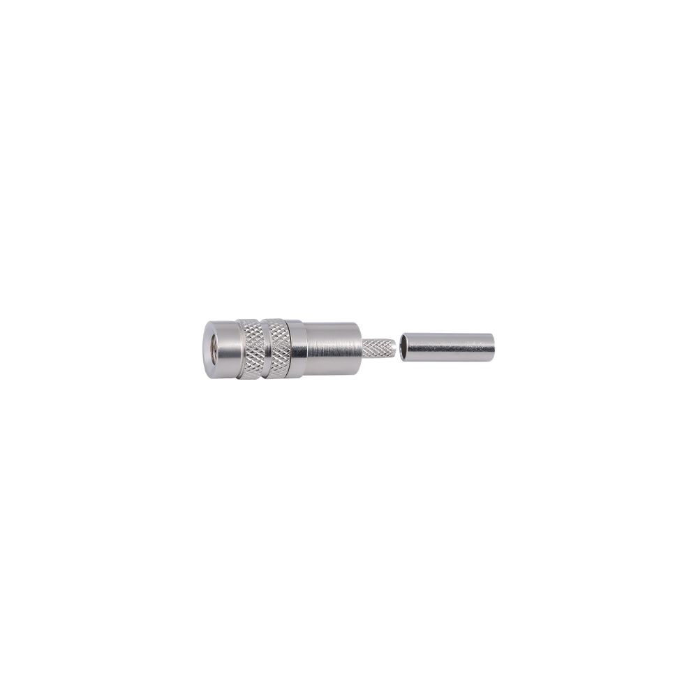
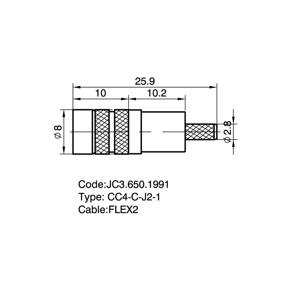
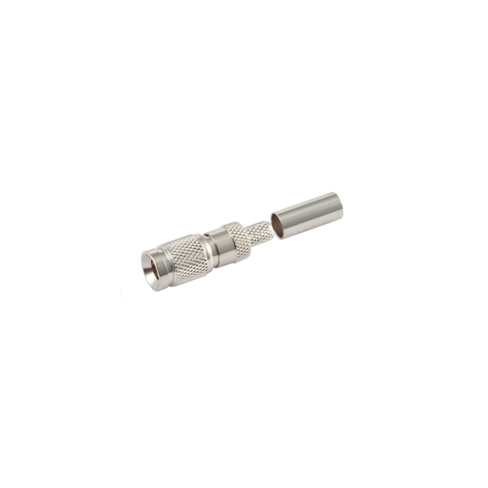
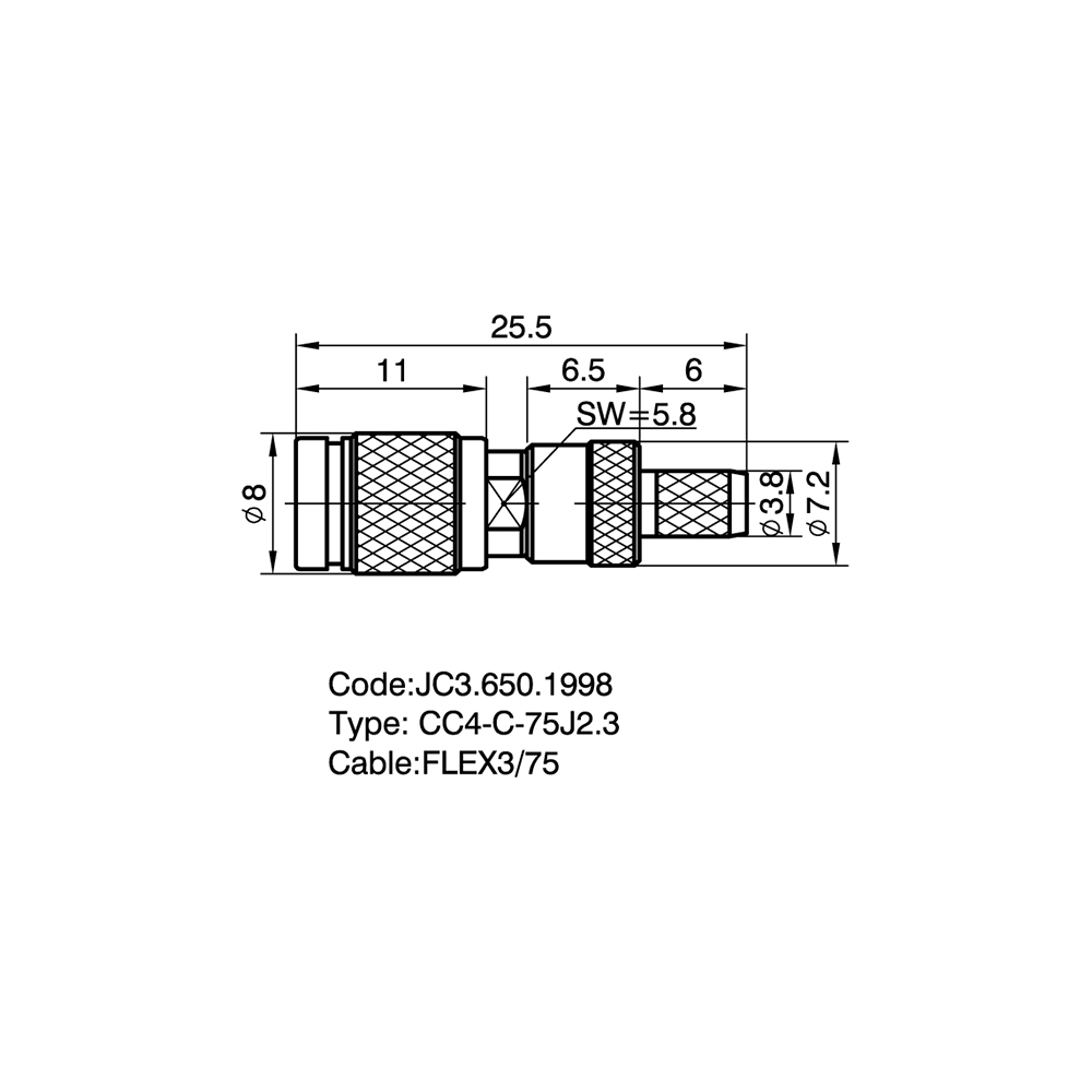
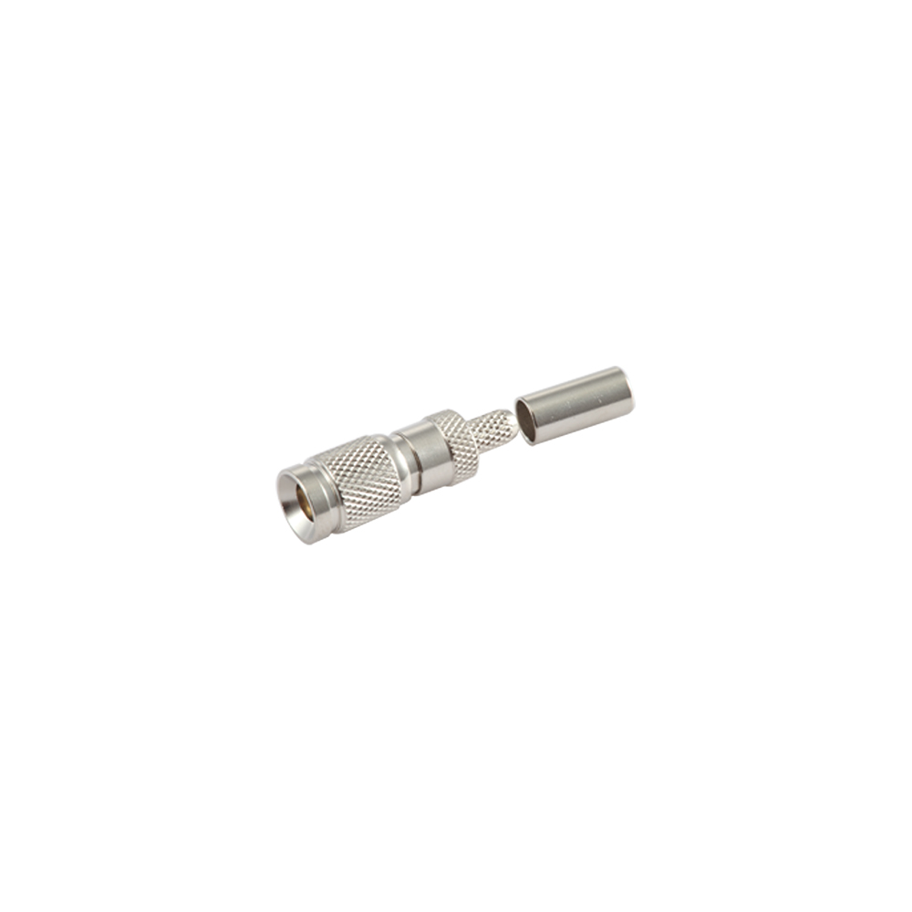
CC4 connectors for flexible cable terminate standard flexible coaxial cables to form the RF interface between cable assemblies and equipment. The snap-on mating mechanism makes both ends of a jumper fast to connect and disconnect, which is a practical advantage in systems that require frequent re-routing or rapid deployment. Solder and crimp termination styles are available to suit different production workflows.

Key Features
Solder and crimp termination options for small-batch or automated high-volume production
Compatible with multiple standard flexible coaxial cable outer diameters
Snap-on connection requires no tools
Uniform plating for long-term oxidation resistance on contact surfaces

Competitive Advantages
Cable available alongside connectors for one-stop procurement
Custom jumper assembly service available: crimp/solder, electrical test, and packaging
Extensive export experience with established documentation for US, Japanese, and European orders

Typical Applications
Inter-module jumper cables inside communication racks
RF patch cables for digital distribution frames
Instrument calibration cables
Data monitoring system RF signal connections

FAQ
Q: When should I choose crimp over solder termination?
A: Crimp is better suited for high-volume production: consistent results, no open flame, and faster cycle time. Solder suits small batches or field repair where tooling flexibility matters. Electrical performance is comparable between the two.
Q: Which cable models are compatible?
A: Please provide the cable outer diameter, inner conductor diameter, and shield construction. Our sales or technical team will identify the matching connector to avoid assembly issues from mismatched tolerances.
Q: Is the snap-on lock secure enough — could it release accidentally?
A: The CC4 snap-on mechanism is designed to maintain reliable retention under normal use. If your application involves significant vibration or shock, please describe the conditions so our team can confirm suitability or recommend a locking variant.
Q: Can jumper length be customized?
A: Yes. Custom jumpers can be specified by length, connector type at each end, and impedance.
Q: Can I order 50 Ohm and 75 Ohm versions on the same purchase order?
A: Yes. Please indicate the required impedance, model, and quantity for each line item in your inquiry.
Q: What is the typical lead time?
A: Standard models ship from stock when available. Custom cable assemblies require production scheduling; please align timelines with the sales team in advance.
About
Yangzhou Jingcheng Electronics Co., Ltd.

Yangzhou Jingcheng Electronics Co., Ltd., a premier China 1.0/2.3(CC4) Connectors for flexible cable Manufacturer and 1.0/2.3(CC4) Connectors for flexible cable Supplier, was founded in 1999. It is a high-tech enterprise specializing in the R&D and manufacturing of RF coaxial connectors, cable assemblies, and passive microwave components.
Equipped with a comprehensive R&D and production system, the company has obtained international certifications including ISO9001. Adhering strictly to standards such as MIL, IEC and GB, we offer over 30 product series with more than 2,000 specifications, covering SMA, BNC, N-type and other mainstream models. Our products are widely applied in the fields of communications, aerospace, automotive electronics and beyond, and exported to many countries and regions across Europe, America and Asia.
We uphold the tenet of "Quality as the Foundation, Customers as the Core", committed to providing reliable interconnection solutions and professional services for global clients.

1.0/2.3(CC4) Connectors for flexible cable Industry knowledge

1.0/2.3 (CC4) connectors are miniature, threaded-coupling RF coaxial connectors used to join flexible cable to equipment ports. The series takes its name from its dimensions: a 1.0mm center conductor and a 2.3mm outer conductor, held at a constant 50Ω impedance from DC to 11GHz. Because of this compact footprint, 1.0/2.3 (CC4) connectors are commonly selected for base station jumpers, distributed antenna nodes, and test interfaces where panel space is limited.

Compared with SMA or N-type connectors covering a similar frequency range, 1.0/2.3 (CC4) connectors occupy noticeably less panel space, which is a primary reason the series is chosen for equipment racks and antenna nodes where multiple RF lines run close together.

Yangzhou Jingcheng Electronics Co., Ltd has manufactured RF coaxial connectors and cable assemblies since 1999, producing the 1.0/2.3 (CC4) series and matched cable assemblies under MIL, IEC, and GB standards, across more than 30 series and 2,000 specifications.

Working Principle

The center and outer conductors share a common axis, confining the RF field between them and setting the connector's 50Ω impedance. A low-loss dielectric, typically PTFE, keeps this impedance constant and limits signal reflection along the transmission path.

Coupling and Shielding

The threaded outer conductor applies steady contact pressure at the mating interface, resisting loosening under vibration or repeated cable flexing. It also forms a continuous shield with the cable braid, containing the RF field and blocking external interference. Crimp or solder terminations join the connector to the cable's center conductor, braid, and jacket, extending the same 50Ω path through the mechanical joint.

Application Cases

1.0/2.3 (CC4) connectors are applied across several RF and communication scenarios:

  • Base station jumper cables connecting Remote Radio Units to antenna feeder lines
  • Distributed Antenna System links between coverage nodes and combiners or splitters
  • Test and measurement interfaces between RF modules and bench instruments
  • Vehicle-mounted and industrial modules with restricted connector space

Comparison with Related Connectors

Compared with other 50Ω miniature connector types, the threaded coupling of 1.0/2.3 (CC4) connectors gives higher stability under vibration, along with a wider frequency range than snap-on alternatives, making the series more suited to outdoor and base station installations than to board-level connections.

Comparison of 1.0/2.3 (CC4) connectors with other miniature 50Ω connector types
Parameter 1.0/2.3 (CC4) Type A Type B Type C
Coupling Threaded Snap-on Snap-on Snap-on
Frequency range DC–11GHz DC–6GHz DC–6GHz DC–4GHz
Relative size Small Smaller Smallest Medium
Typical use Base station, DAS Portable devices Dense PCB layouts Instrumentation

Maintenance Guidance

  1. Tighten connectors with a calibrated torque wrench to the range stated in the datasheet; under-torquing causes poor contact, over-torquing damages the threads.
  2. Seal outdoor or humid connections with waterproof tape or heat-shrink tubing to prevent moisture ingress and oxidation.
  3. Check insertion loss and return loss periodically with a vector network analyzer on long-service connections.
  4. Keep the flexible cable above its minimum bend radius near the connector base to avoid core wire or shield damage.
  5. Fit dust caps when connectors are not in use and clean contact surfaces with anhydrous ethanol only.

Frequently Asked Questions

Are 1.0/2.3 connectors and CC4 connectors the same product?

Yes. CC4 is an alternative industry name for the 1.0/2.3 connector, referring to the same structure and standard.

Can custom cable assemblies be produced for this series?

Cable assemblies can be configured to cable model, length, and interface combination. Providing an equipment interface drawing or an original connector sample helps confirm the specification.

What materials are used in 1.0/2.3 (CC4) connectors?

The outer conductor is commonly nickel- or gold-plated brass, the center conductor is typically gold-plated phosphor bronze, and the insulator is generally PTFE, with the combination varying by model and operating environment.

How should signal instability at a connector be diagnosed?

Check first that the connection is fully tightened and free of oxidation or debris, then measure insertion loss and return loss with a network analyzer to isolate the connector body from the cable's solder or crimp joint.