SMA RF Coaxial Connectors Wholesale

Home / Products / Coaxial Connectors / SMA RF Coaxial Connectors

SMA RF Coaxial Connectors Manufacturer

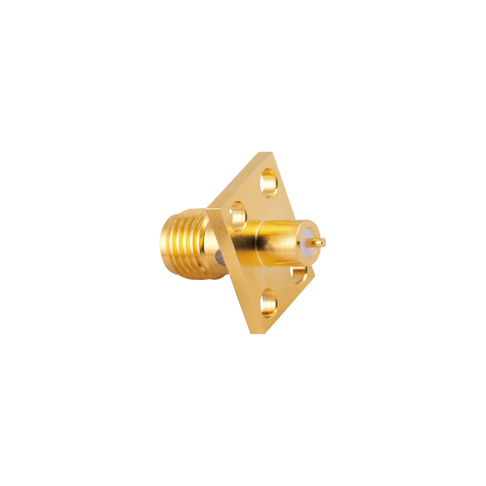
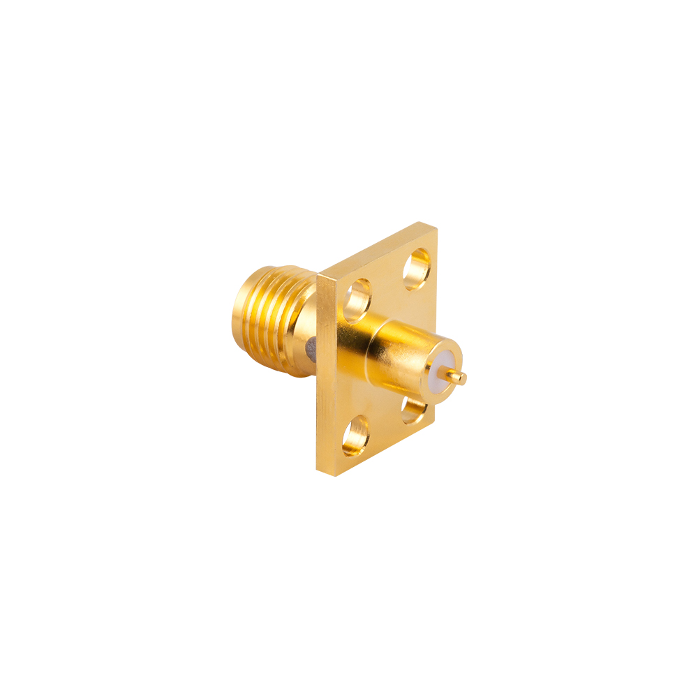
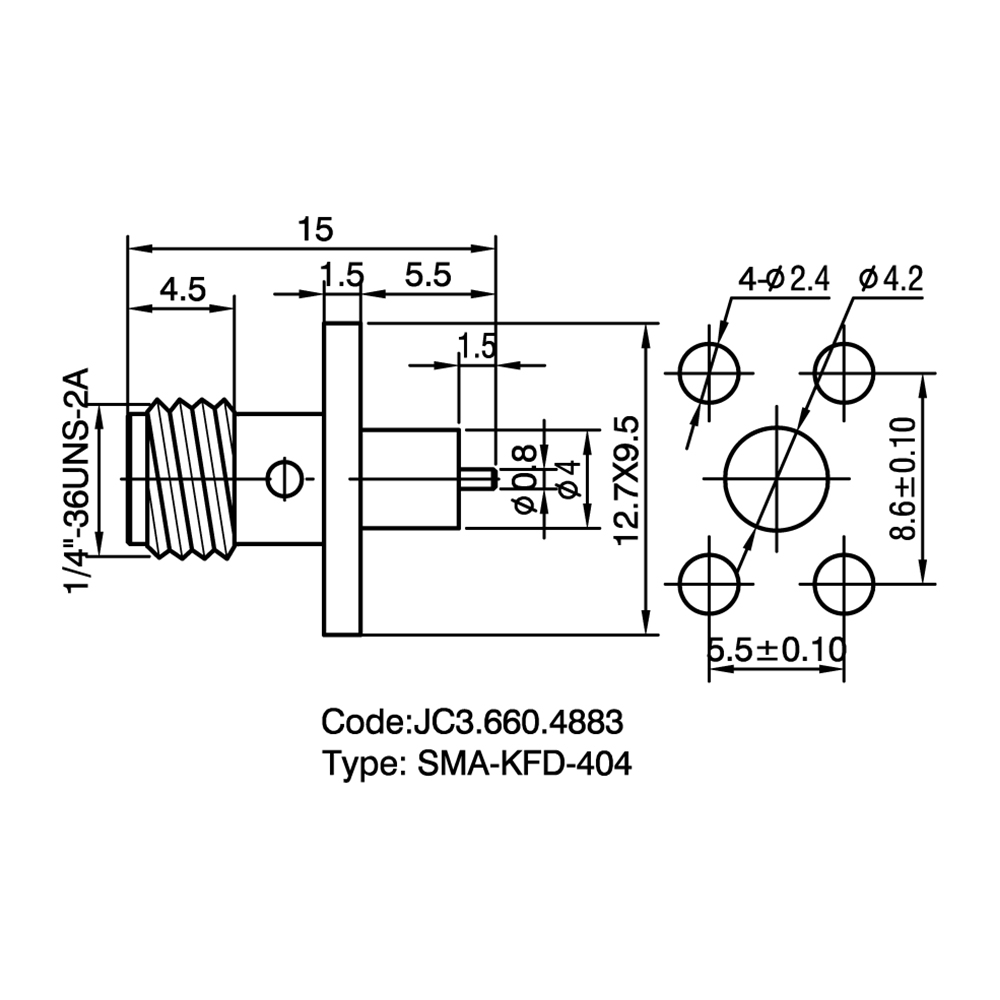
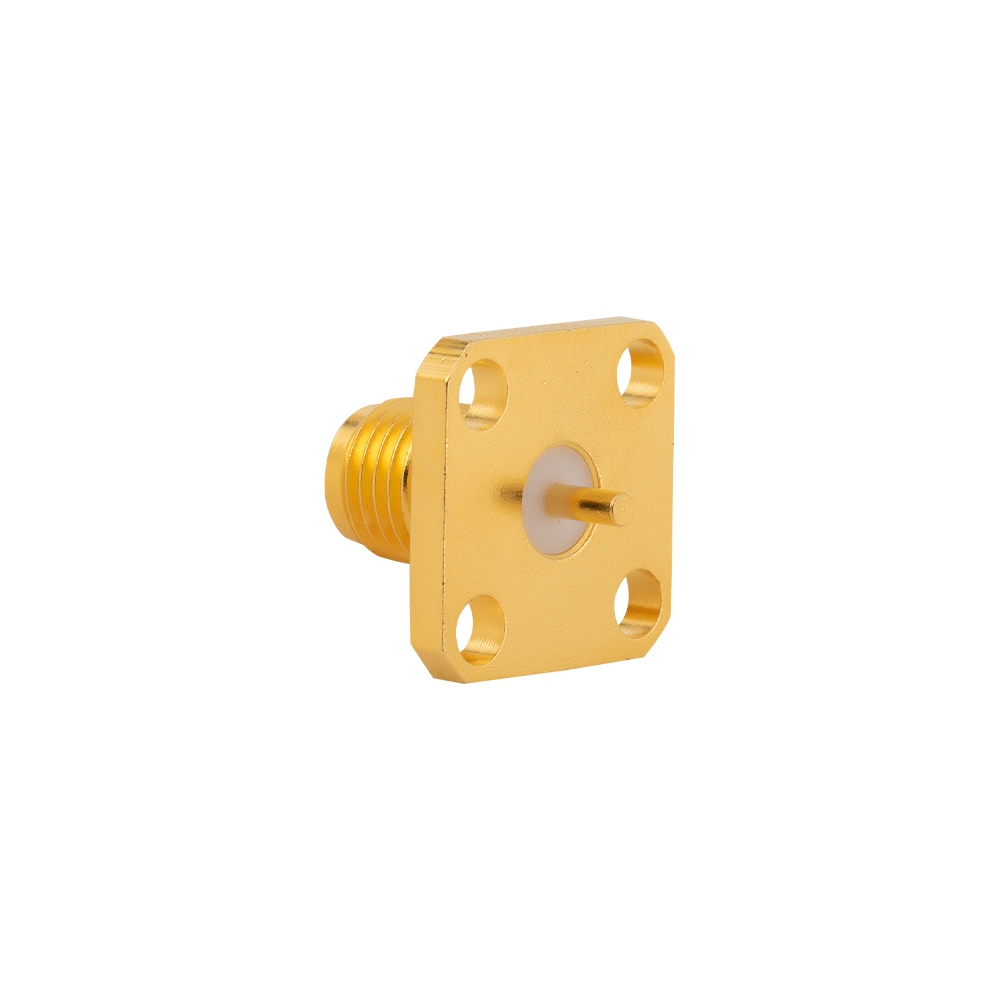
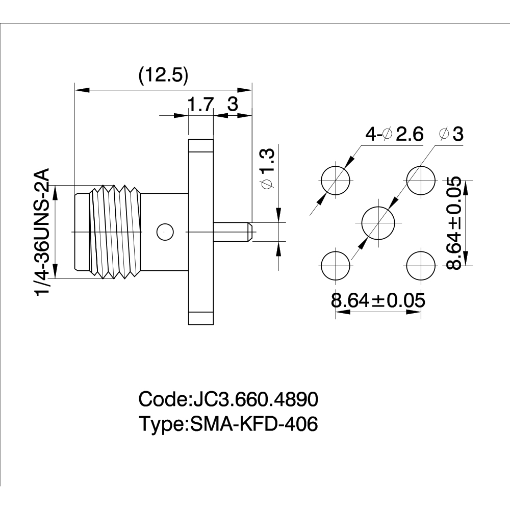
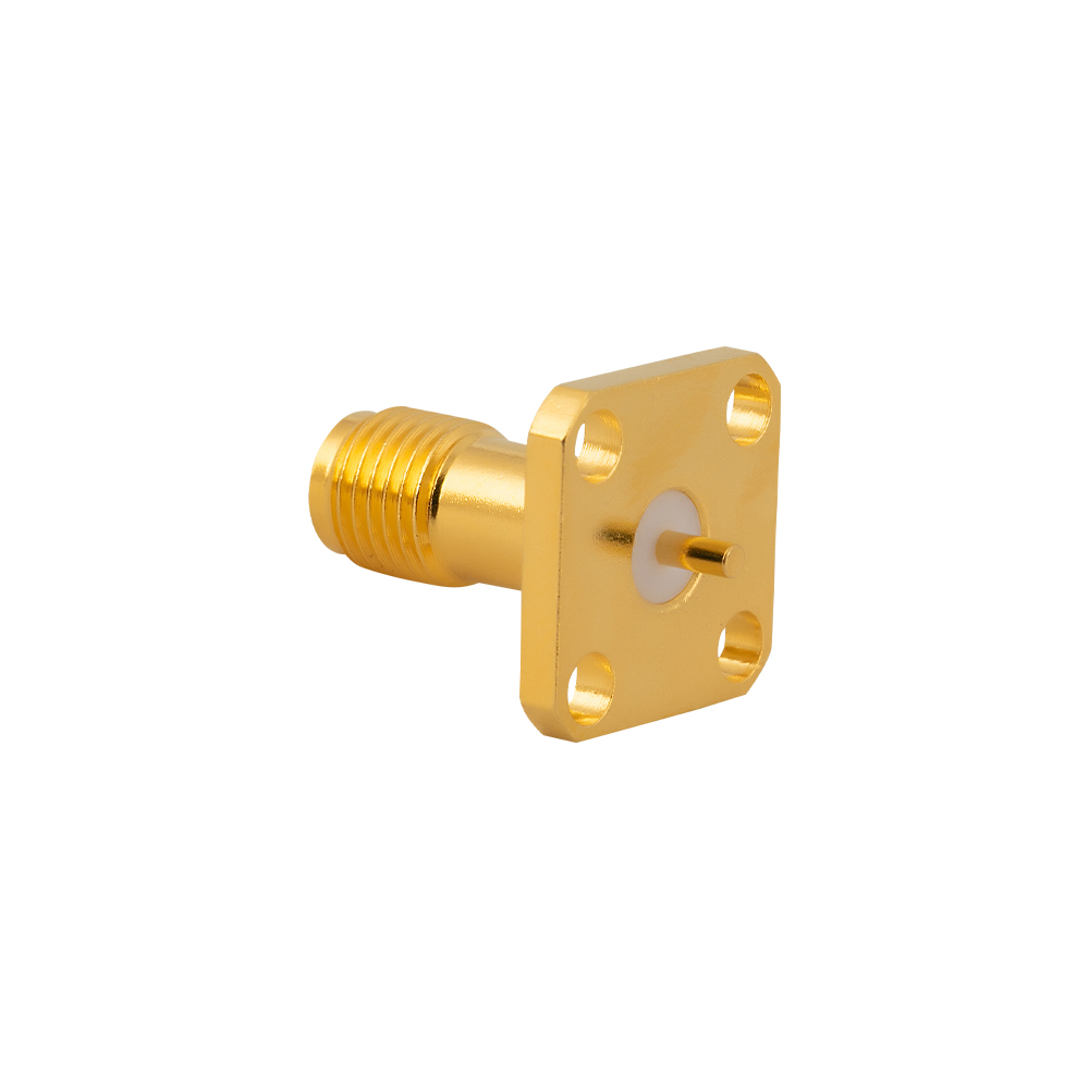
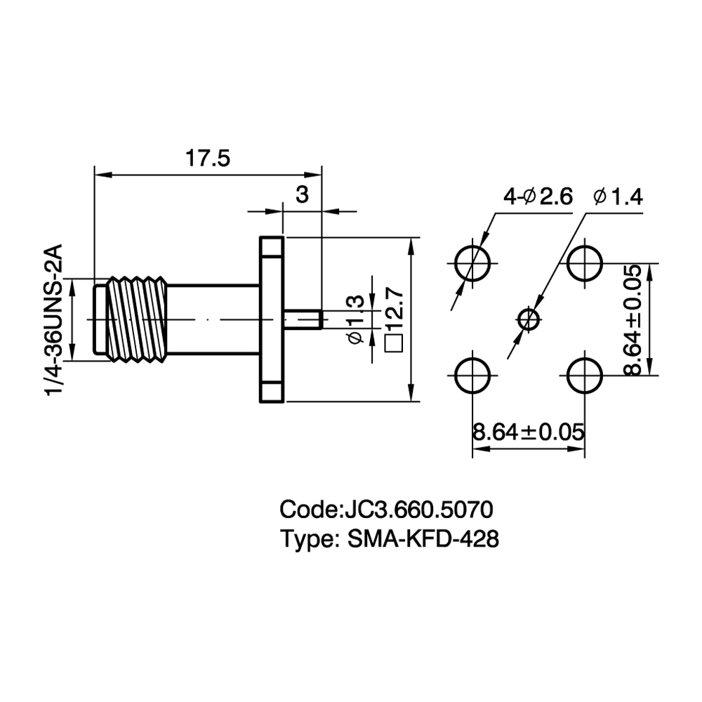
TYPE SMA is one kind of RF coaxial Connectors that is widely applied, with Small-sized thread coupling. Characteristic impedance is 50Ώ. The characteristic of connector is in wide frequency range, excellent Performance, high reliability. They are used in connection with RF cable or micro-strip line in RF circuit of the WLAN system, controlled program, microwave equipment and digital communication system. The frequency can be up to 18GHz by using semi-rigid or semi-flex cable.

Temperature  Range

-55~+155℃(PE Cable   -40~+85℃)

Impedance

50Ω

Frequency Range

DC~12.4GHz(Semi-Rigid Cable DC~18GHz)

Insulation resistance

≥5000MΩ

Insertion loss

≤0.15  dB/6GHz

Voltage Standing Wave Ratio (VSWR)

Straight  Flexible cable≤1.10+0.02f

Semi-Rigid Cable≤1.07+0.018f

Right  angle Flexible cable≤1.20+0.03f

Semi-Rigid Cable≤≤1.17+0.02f

Durability(mating)

≥500cycles

About
Yangzhou Jingcheng Electronics Co., Ltd.

Yangzhou Jingcheng Electronics Co., Ltd., a premier China SMA RF Coaxial Connectors Manufacturer and SMA RF Coaxial Connectors Factory, was founded in 1999. It is a high-tech enterprise specializing in the R&D and manufacturing of RF coaxial connectors, cable assemblies, and passive microwave components.
Equipped with a comprehensive R&D and production system, the company has obtained international certifications including ISO9001. Adhering strictly to standards such as MIL, IEC and GB, we offer over 30 product series with more than 2,000 specifications, covering SMA, BNC, N-type and other mainstream models. Our products are widely applied in the fields of communications, aerospace, automotive electronics and beyond, and exported to many countries and regions across Europe, America and Asia.
We uphold the tenet of "Quality as the Foundation, Customers as the Core", committed to providing reliable interconnection solutions and professional services for global clients.

News & Updates
SMA RF Coaxial Connectors Industry knowledge

Category Overview

SMA RF Coaxial Connectors (SubMiniature version A) are semi-precision, threaded-interface radio frequency connectors operating with a characteristic impedance of 50 ohms. They utilize a 1/4-36 UNS threaded coupling mechanism that ensures secure mating and consistent electrical performance across a broad frequency range, typically from DC to 18 GHz, with precision-grade variants extending to 26.5 GHz. The connector's outer diameter of approximately 6.35 mm (0.25 inch) provides a balance between compact size and mechanical robustness, making it one of the most widely adopted coaxial connector interfaces in RF and microwave engineering.

Yangzhou Jingcheng Electronics (JC), established in 1999, manufactures SMA RF Coaxial Connectors as a core product line within its comprehensive portfolio of RF coaxial interconnect solutions. The production of these connectors at JC is supported by advanced manufacturing equipment, precision high-frequency testing instrumentation, and a dedicated technical team. The threaded coupling design provides high resistance to vibration and unintentional disconnection, while the standardized interface dimensions enable intermateability with connectors produced to the same specification. JC's SMA connectors are available in a variety of configurations, including straight and right-angle PCB mounts, bulkhead panel mounts, SMT versions, and cable-attachment types for flexible and semi-rigid cable assemblies.

SMA RF Coaxial Connectors are utilized across a wide spectrum of applications, including wireless base station infrastructure, test and measurement instrumentation, antenna feed systems, microwave point-to-point links, military and aerospace communication equipment, automotive radar modules, and medical imaging devices. Their combination of moderate size, high-frequency capability, and threaded reliability makes them suitable for both development laboratory environments and high-volume commercial deployment.

Common Types & Configurations

Connector Type Mounting / Termination Typical Body Material Key Characteristics
PCB Vertical Mount Through-hole soldering, straight orientation Brass or stainless steel Mating axis perpendicular to PCB plane; robust mechanical retention via multiple ground legs; suitable for top-side access panels.
PCB Right-Angle Mount Through-hole soldering, right-angle orientation Brass, zinc alloy or stainless steel Mating axis parallel to PCB; reduces enclosure height; commonly used in edge-panel I/O configurations.
SMT (Surface-Mount) Surface-mount soldering, straight or right-angle Brass with high-temperature insulator Compatible with reflow soldering and automated assembly; requires well-designed pad layout; may include enhanced ground solder tabs.
Edge-Mount / End-Launch Soldered to PCB edge pads Brass or stainless steel Direct transition from PCB transmission line to coaxial interface; minimizes signal path discontinuity at board edge.
Bulkhead / Panel Mount Mounts through panel with nut and washer; internal cable or PCB connection Stainless steel or brass Provides external access through enclosure walls; available with extended dielectric and various flange styles.
Cable Connector (Plug/Jack) Crimp, clamp, or solder attachment for flexible or semi-rigid cables Brass or stainless steel Designed to terminate common coaxial cable types (RG-316, RG-174, RG-58, semi-rigid 0.141"); available as straight or right-angle versions.
Reverse Polarity SMA (RP-SMA) Same mounting types as standard SMA Brass, often with nickel body Gender-reversed center contact arrangement (male body with female contact or vice versa); widely used in Wi-Fi, WLAN, and ISM band antenna interfaces to prevent unauthorized antenna connections.

Comparative Analysis

3.1 SMA vs. Precision Coaxial Connectors (3.5 mm / 2.92 mm)

Parameter SMA Connector 3.5 mm Connector 2.92 mm Connector
Frequency Range DC to 18 GHz (26.5 GHz typical limit) DC to 34 GHz DC to 40 GHz
Interface Dimensions Outer conductor ID 4.13 mm, dielectric diameter 1.27 mm (PTFE) Same outer conductor dimensions as SMA; uses air dielectric Smaller internal dimensions; air dielectric
Dielectric Type PTFE (solid dielectric) Air (with dielectric support beads) Air
Mating Compatibility Mates with 3.5 mm (with caution); not recommended with 2.92 mm Mates mechanically with SMA but may damage SMA socket Not mechanically compatible with SMA
Typical Application General RF, test equipment, base stations Metrology, calibration kits, precision measurements Millimeter-wave modules, 5G sub-40 GHz
Cost Position Cost-effective for high-volume use Higher cost (precision manufacturing) Higher cost

3.2 SMA vs. BNC vs. TNC

Parameter SMA BNC TNC
Coupling Type Threaded Bayonet (quick connect) Threaded
Frequency Range DC to 18 GHz (26.5 GHz) DC to 4 GHz (typically) DC to 11 GHz (typically)
Size (Outer Diameter) ~6.35 mm ~10 mm ~10 mm (threaded variant of BNC)
Vibration Resistance Excellent (threaded) Moderate (bayonet can loosen) Excellent (threaded)
Typical Use Microwave, high-frequency test Broadcast, video, low-frequency RF Mobile communications, antennas

3.3 Standard SMA vs. Reverse Polarity SMA (RP-SMA)

Feature Standard SMA Reverse Polarity SMA (RP-SMA)
Center Contact Gender Male plug: male pin; female jack: female socket RP male plug: female socket in male body; RP female jack: male pin in female body
Threaded Shell Gender Male plug has external threads; female jack has internal threads Same shell gender convention as standard SMA
Primary Application General RF and microwave systems Consumer Wi-Fi / WLAN access points, routers, and antenna interfaces (FCC compliance)
Electrical Performance Same RF performance characteristics up to rated frequency Identical RF performance to standard SMA
Mating Compatibility Mates only with standard SMA Mates only with reverse polarity SMA

Application Scenarios

SMA RF Coaxial Connectors serve a broad range of industries and equipment types due to their high-frequency capability, threaded reliability, and moderate form factor. Common deployment scenarios include:

• Test & Measurement Instrumentation

Standard interface on vector network analyzers, spectrum analyzers, signal generators, and oscilloscope probes up to 18 GHz or higher.

• Wireless Base Station Infrastructure

Used in RF modules, duplexers, filters, and feed systems within cellular base stations operating in sub-6 GHz and microwave bands.

• Antenna Feeder Systems

Connects antennas to transceivers in point-to-point microwave links, satellite communications, and radar installations.

• Wi-Fi & ISM Band Equipment

RP-SMA variants are standard antenna connectors on Wi-Fi routers, access points, and IoT gateways operating at 2.4 GHz and 5 GHz.

• Military & Aerospace

Deployed in avionics, radar systems, and electronic warfare equipment where threaded coupling ensures connection integrity under vibration.

• Automotive Radar & ADAS

Utilized in 24 GHz and 77 GHz radar sensor modules for advanced driver-assistance systems; often adapted with high-frequency precision variants.

• Medical Imaging Equipment

Used in MRI and other diagnostic imaging systems for RF signal transmission within shielded enclosures.

Selection Guide & Key Considerations

Choosing the correct SMA RF Coaxial Connector configuration involves evaluating multiple technical and mechanical factors. Yangzhou Jingcheng Electronics provides engineering consultation to assist in selecting the appropriate SMA connector from its product lines. The following parameters should be assessed during the selection process:

Selection Criterion Description Guidance
Frequency Range The maximum operating frequency and required bandwidth. Standard SMA connectors perform to 18 GHz; precision-grade SMA extends to 26.5 GHz. For applications above 26.5 GHz, consider 2.92 mm or 2.4 mm interfaces.
Polarity Type Standard or reverse polarity (RP) configuration. Standard SMA is used for general RF applications. RP-SMA is mandated by regulation for many consumer Wi-Fi devices; verify equipment interface requirements.
Mounting Configuration PCB layout, panel cutout, or cable termination method. Select vertical, right-angle, edge-mount, or bulkhead types based on mechanical design. Match PCB footprint to connector variant (through-hole, SMT).
Cable Compatibility Coaxial cable type if attaching a cable connector. Cable connectors are designed for specific cable diameters and constructions (e.g., RG-316, RG-174, RG-58, LMR-240, semi-rigid). Verify cable dimensions before selection.
Body Material Material and plating of the connector body. Brass with nickel or gold plating is standard; stainless steel offers higher durability and corrosion resistance for harsh environments.
Impedance Characteristic impedance of the connector. Standard SMA impedance is 50 ohms. Ensure system impedance matching to minimize reflection.
VSWR / Return Loss Impedance matching performance over frequency. Typical SMA VSWR is ≤ 1.3:1 up to 18 GHz. For precision applications, specify connectors with lower VSWR specifications.
Mating Cycle Life Expected number of connect/disconnect operations. Standard rating is 500 cycles minimum for brass connectors; stainless steel variants may offer extended cycle life.
Environmental Sealing Protection against moisture and contaminants. For outdoor or harsh environments, consider connectors with IP-rated sealing gaskets or weatherproof boots.

Frequently Asked Questions

Q1: What is the typical frequency range of an SMA RF Coaxial Connector?

Standard SMA connectors are rated from DC to 18 GHz, with precision versions extending performance to 26.5 GHz. The upper usable frequency is determined by the PTFE dielectric and the onset of higher-order propagation modes within the connector. Yangzhou Jingcheng Electronics manufactures SMA connectors designed to meet VSWR and insertion loss specifications across these frequency bands.

Q2: What is a Reverse Polarity SMA (RP-SMA) connector and where is it used?

A Reverse Polarity SMA connector reverses the gender of the center contact while maintaining the same outer shell threading. An RP-SMA male plug has a female center socket inside a male threaded body. This configuration was introduced to prevent end-users from connecting higher-gain antennas to Wi-Fi devices, ensuring compliance with regulatory emission limits. RP-SMA is the standard antenna interface on most consumer wireless LAN equipment.

Q3: Are SMA connectors compatible with 3.5 mm and 2.92 mm connectors?

Mechanically, an SMA male can mate with a 3.5 mm female because they share the same outer conductor dimensions; however, the 3.5 mm female uses a thinner inner contact that can be damaged by the larger pin of an SMA male. 2.92 mm connectors have different internal dimensions and are not mechanically compatible with SMA. It is generally recommended to mate connectors of the same type and precision grade to avoid damage and ensure specified electrical performance.

Q4: What torque should be applied when mating SMA connectors?

The recommended mating torque for SMA connectors is typically 5 to 8 inch-pounds (0.56 to 0.9 N·m). Using a calibrated torque wrench helps ensure consistent contact pressure and prevents damage from over-tightening. Applying the correct torque is important for achieving repeatable electrical performance, especially in test and measurement setups.

Q5: What materials are used in SMA connector construction?

Typical SMA connector bodies are made from brass or stainless steel, with plating options including nickel, gold, or passivated stainless steel. Center contacts are generally beryllium copper or brass with gold plating. The dielectric material is PTFE. The choice of materials influences connector durability, corrosion resistance, and cost. JC offers SMA connectors in multiple material and plating configurations to suit different application requirements.

Q6: How many mating cycles can an SMA connector typically withstand?

Standard brass SMA connectors are typically rated for 500 mating cycles while maintaining specified electrical performance. Stainless steel SMA connectors, due to their harder surface, can often exceed this cycle count. Actual durability depends on factors including mating torque, cleanliness, and environmental conditions. For high-cycle applications, contacting the manufacturer for extended-life product recommendations is advised.

Technical Notes

  • The SMA interface uses a 1/4-36 UNS threaded coupling nut that provides secure, vibration-resistant connection. Proper thread engagement is critical for maintaining consistent ground contact and impedance continuity.
  • SMA connectors with PTFE dielectric can exhibit a small impedance discontinuity at the bead support; precision air-interface connectors (3.5 mm, 2.92 mm) minimize this effect for higher-frequency measurements.
  • When soldering SMA PCB connectors, controlled soldering temperatures and durations are important to prevent dielectric melting or contact pin misalignment, particularly with PTFE insulators.
  • For applications above 18 GHz, the mode-free operation of the connector should be verified; slight dimensional variations can introduce higher-order modes that degrade transmission performance.
  • Yangzhou Jingcheng Electronics, with manufacturing operations established in 1999, maintains in-house RF testing capability up to 50 GHz, including VSWR, insertion loss, and isolation measurements, ensuring that SMA RF Coaxial Connectors meet their specified performance parameters.