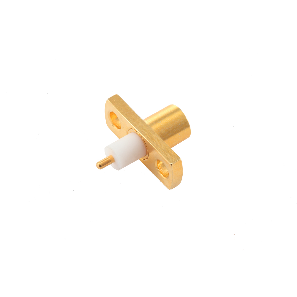
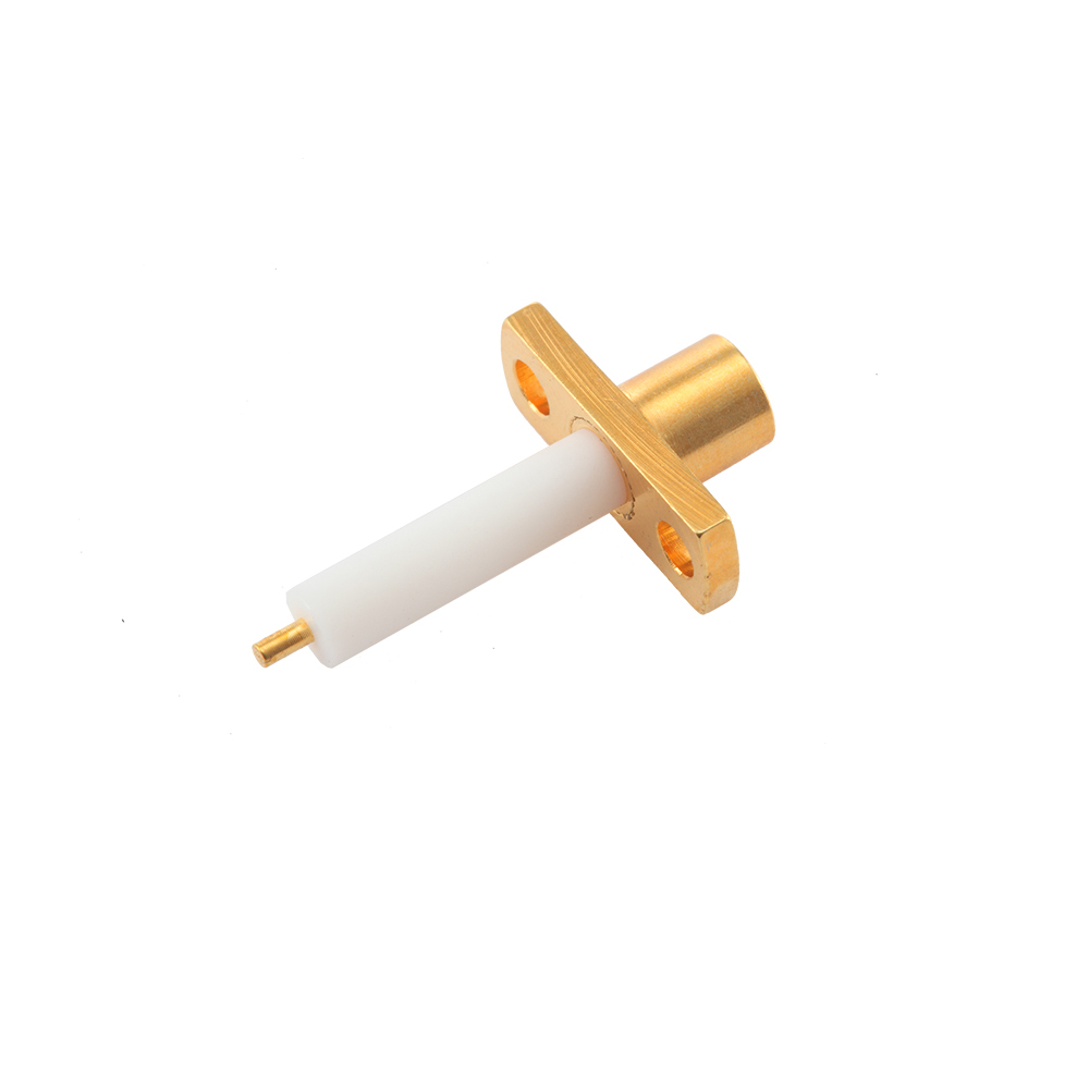
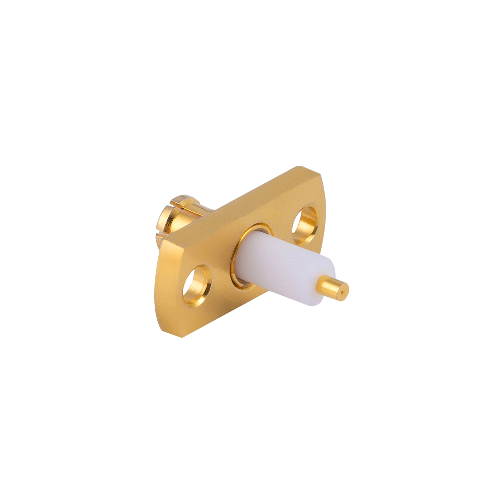
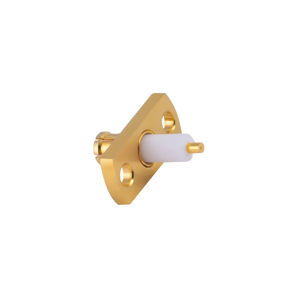
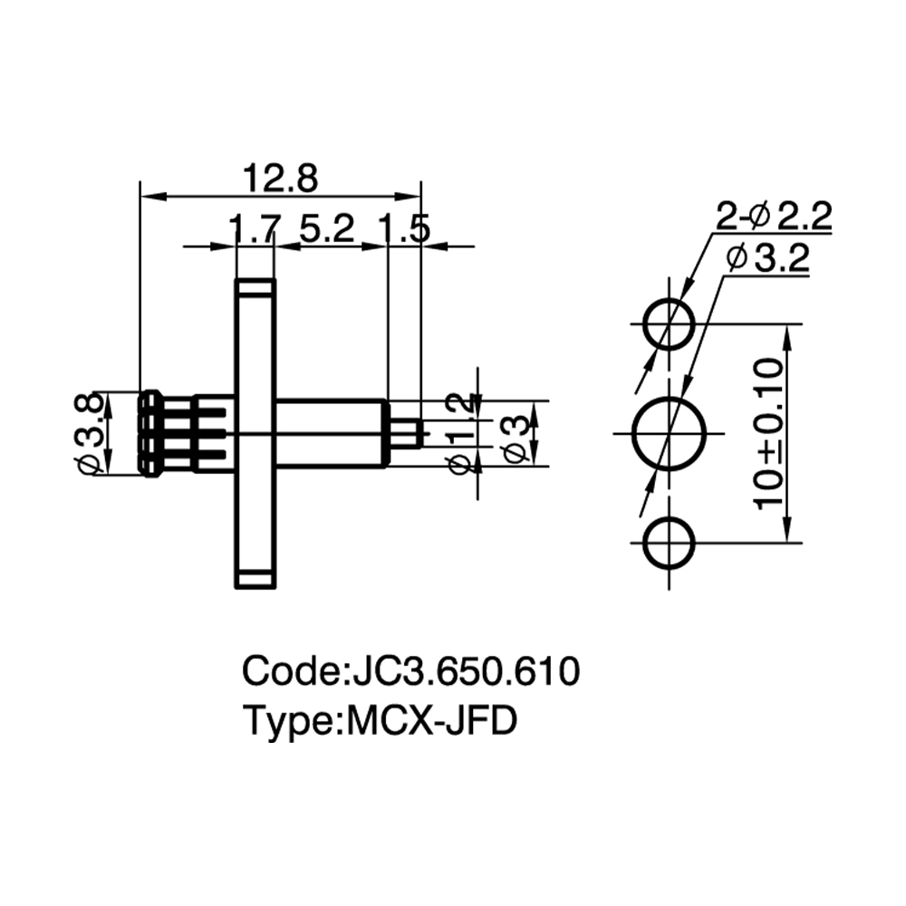
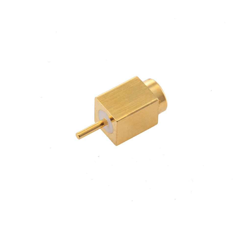
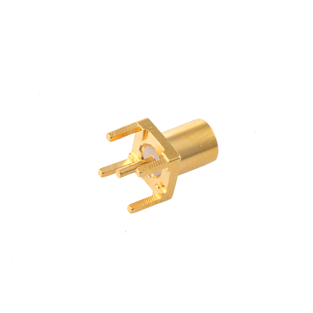
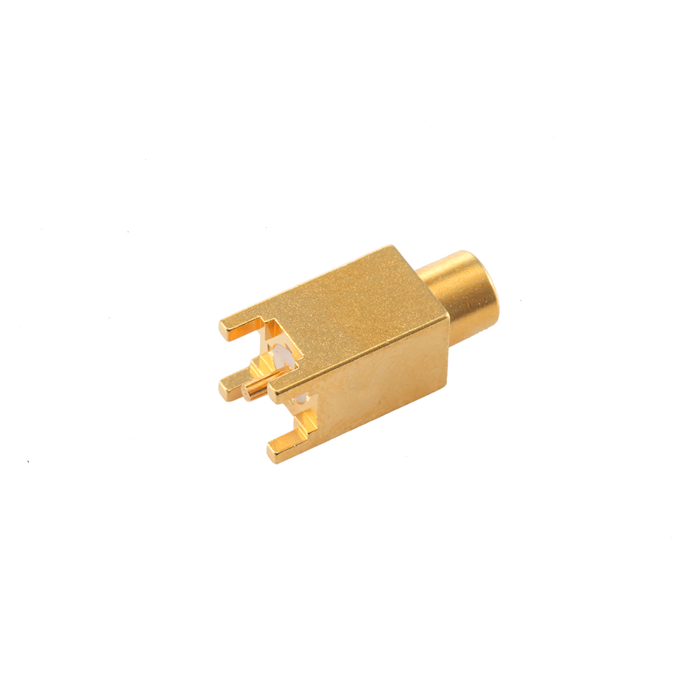
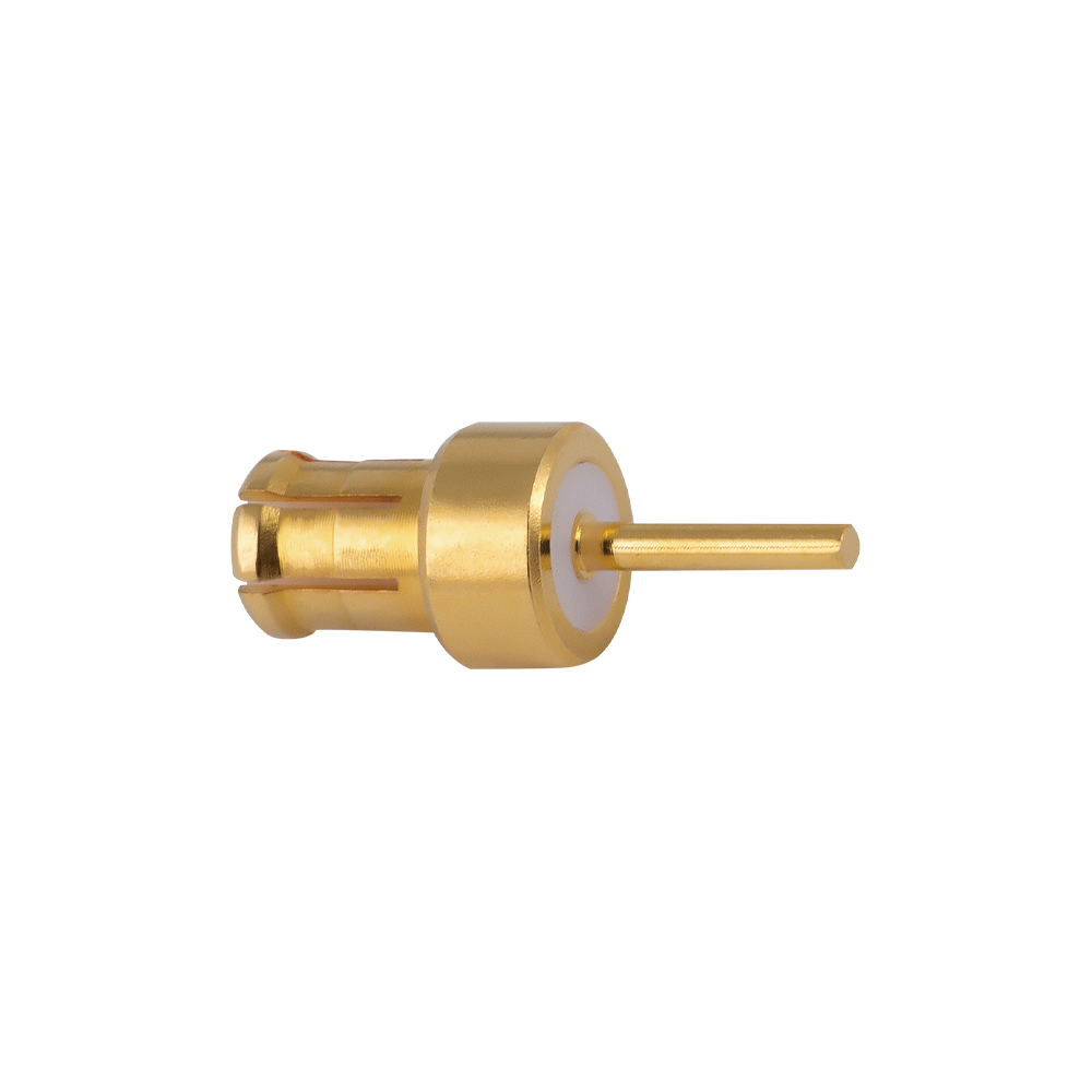
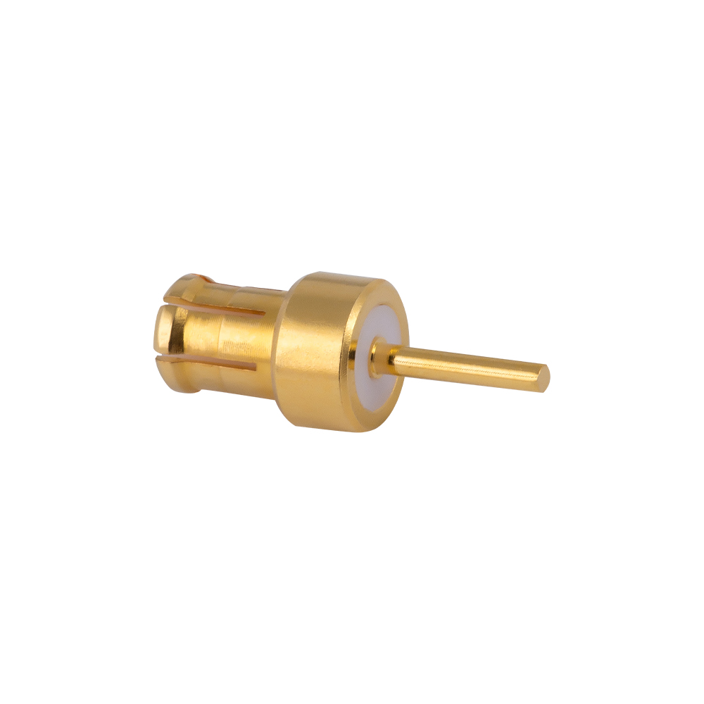
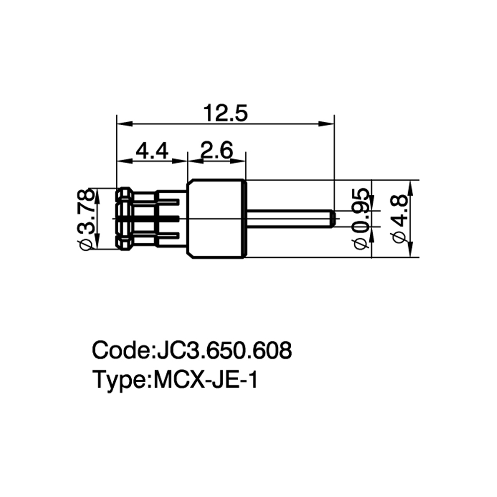
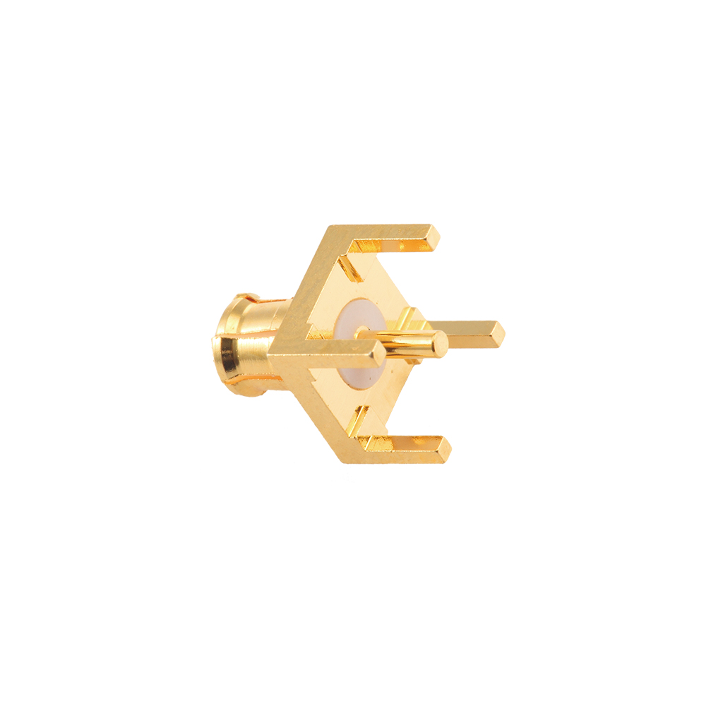
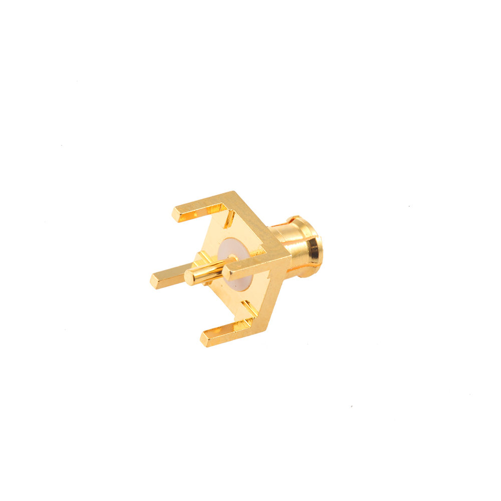
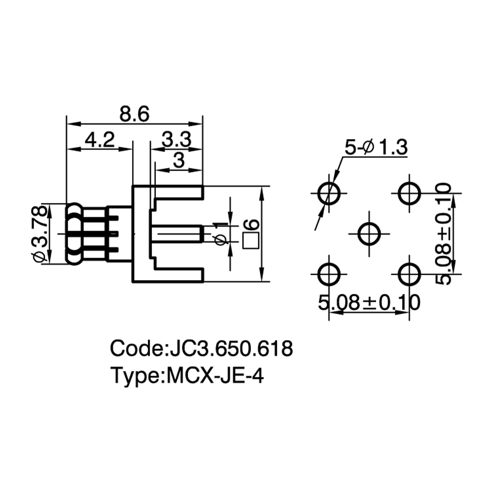
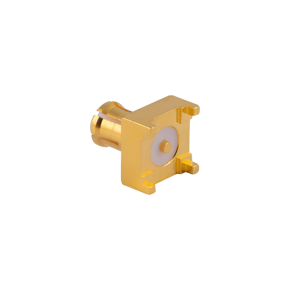
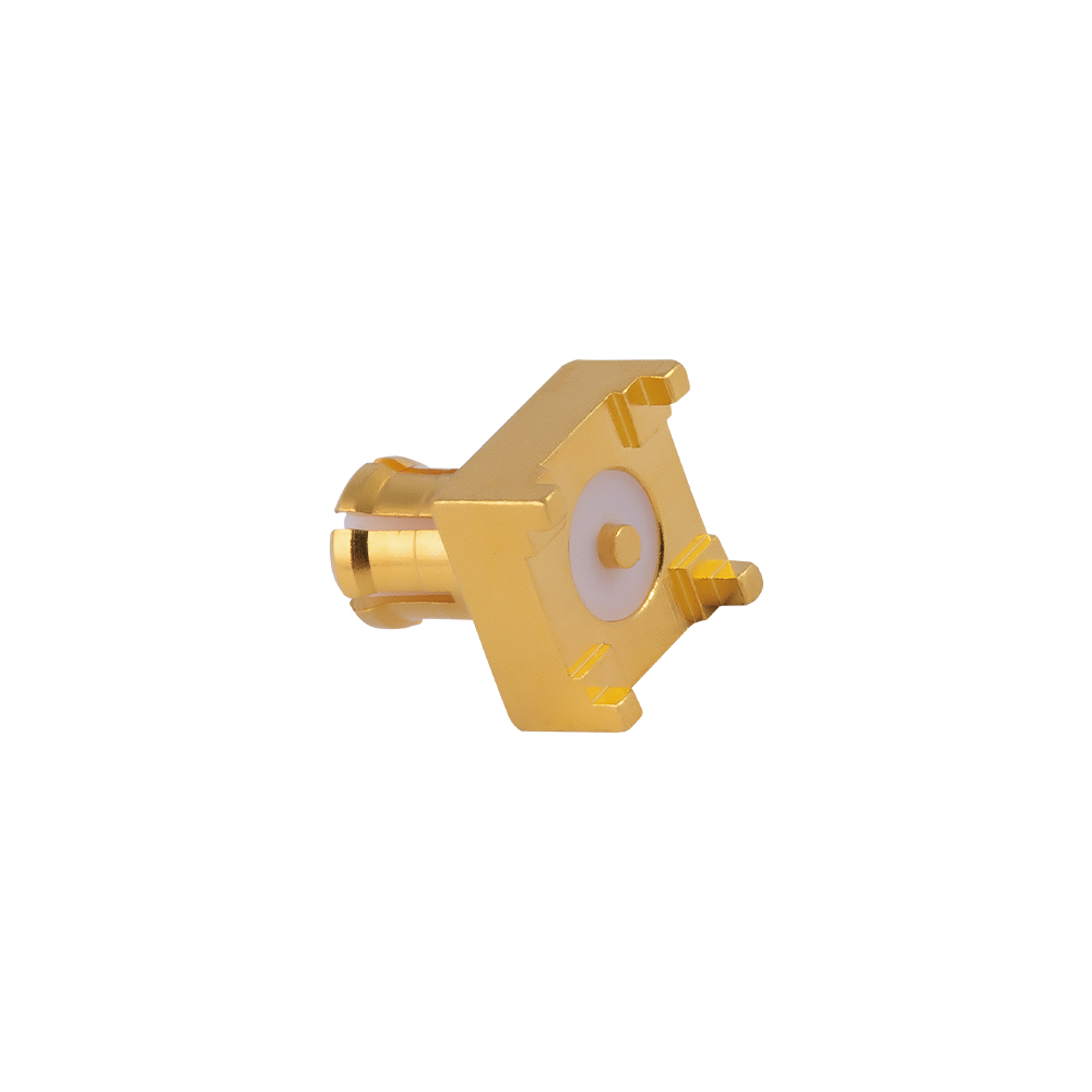
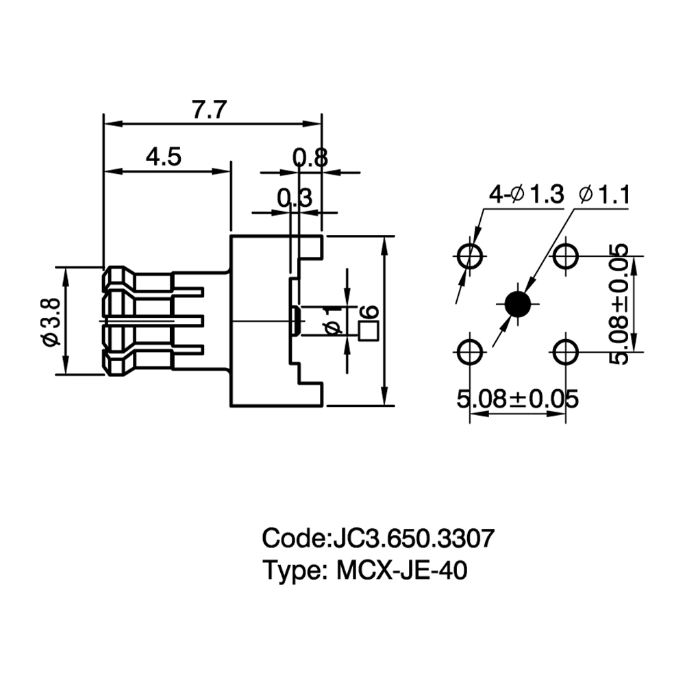
RF Coaxial Connectors are interface components designed to establish repeatable, low-loss electrical connections between RF coaxial cables and devices, modules, or antennas. Their core function is to transmit radio frequency signals within a defined impedance environment while maintaining continuous shielding along the signal path to suppress external electromagnetic interference. Key performance characteristics include characteristic impedance (commonly 50 Ω and 75 Ω), operating frequency range, voltage standing wave ratio (VSWR), insertion loss, and RF leakage. Yangzhou Jingcheng Electronics Co., Ltd. supplies RF Coaxial Connectors and cable assemblies covering DC to 50 GHz, including series such as 2.92 mm, 2.4 mm, 1.85 mm, SMA, N, DIN, BNC, TNC, MCX, MMCX, SMP, reverse polarity connectors and push-pull types.
Common Types and Characteristics
- SMA – Threaded coupling, 50 Ω, typical operating frequency DC–18 GHz (precision versions up to 26.5 GHz). Compact size, widely used in test & measurement and communication modules.
- 3.5 mm, 2.92 mm, 2.4 mm, 1.85 mm – Air-dielectric precision connectors, 50 Ω. 3.5 mm typically reaches 33 GHz, 2.92 mm reaches 40 GHz, 2.4 mm reaches 50 GHz, and 1.85 mm can reach 67 GHz. These share the same outer conductor diameter as SMA and are mechanically mateable, but attention must be paid to mating torque and interface wear.
- N-type – Threaded coupling, available in 50 Ω and 75 Ω. Commonly used up to 11 GHz, precision types can extend beyond 18 GHz. High power handling, suitable for base stations, antenna feeders, and instrumentation.
- DIN 7/16 – Threaded coupling, 50 Ω, typical frequency up to 7.5 GHz. High power capacity and low passive intermodulation (PIM), often deployed in cellular base station antenna systems.
- BNC – Bayonet locking, 50 Ω and 75 Ω versions, frequencies typically up to 4 GHz (some models reach 10 GHz). Quick connect/disconnect, used in video, broadcast, and general-purpose RF instruments.
- TNC – Threaded version of BNC, superior vibration resistance, operating frequency up to 11 GHz or higher, suitable for mobile communications and industrial environments.
- MCX / MMCX – Miniature snap-on connectors, 50 Ω. MCX commonly up to 6 GHz, MMCX up to 6 GHz or higher. MMCX allows 360° rotation, ideal for space-constrained board-to-board connections and GPS modules.
- SMP – Push-on blind-mate connector, 50 Ω, frequency up to 40 GHz, with axial and radial misalignment tolerance, often used in board-to-board, modular systems, and high-density RF arrays.
- UHF – Threaded coupling, non-constant impedance, generally used for low-frequency high-power applications (typically below 500 MHz), common in amateur radio and broadcast systems.
- Reverse Polarity (RP) series – The interface center conductor and receptacle are swapped compared to standard versions, commonly found in WLAN devices to meet regulatory uniqueness requirements for antenna interfaces.
- Push-pull connectors – Lock and release quickly with a push/pull action, eliminating the need for threading. They enable higher mounting density and faster operation, suitable for test cables and medical or semiconductor equipment.
Application Scenarios
RF Coaxial Connectors are extensively deployed in wireless communication base stations (NR / LTE), RF test and measurement systems, aerospace and defense electronics, satellite and navigation terminals (GPS, BeiDou), automotive radar and V2X communication, IoT gateways, digital broadcasting (DVBT), GSM/CDMA modules, and antenna feed networks. Different scenarios impose distinct requirements on power, frequency, PIM, environmental sealing, and mechanical life, making it essential to select connectors according to the actual operating conditions of the interface.
Selection Key Points
- Characteristic impedance matching – Systems usually employ 50 Ω or 75 Ω. Using mismatched connectors introduces reflections, leading to degraded VSWR and reduced link efficiency.
- Frequency range margin – The rated operating frequency of the connector should exceed the highest frequency actually used in the system, allowing headroom to control insertion loss and VSWR.
- Power and PIM requirements – High-power scenarios prefer N-type or DIN 7/16. Cellular antenna feeder systems also demand low-PIM designs.
- Coupling mechanism – Threaded connectors provide vibration resistance and stable intermodulation; bayonet types allow fast mating/unmating; push-on/blind-mate types facilitate high-density installation and modular docking.
- Environmental and mechanical adaptability – For outdoor, humid, or extreme temperature conditions, consider IP protection ratings, salt-spray resistance, and gasket materials.
- Cable compatibility – The connector must match the cable construction (e.g., semi-rigid, semi-flexible, braided outer conductor) and dimensions to ensure electrical and mechanical reliability after soldering or crimping.
- Precision grade and compatibility notes – When mating SMA with 3.5 mm or 2.92 mm connectors, be aware of interface wear risks between different precision grades. For metrology-grade applications, use connectors of the same precision level.
Comparison Examples
| Connector Pair |
Key Differences |
| SMA vs 3.5 mm / 2.92 mm |
All share the same outer conductor diameter and are mechanically mateable, but SMA typically uses a dielectric support while 3.5 mm and 2.92 mm use air dielectric. Frequent inter-mating can damage the precision connector socket and affect measurement accuracy. |
| N-type vs DIN 7/16 |
N-type is smaller with wider available bandwidth; DIN 7/16 offers larger contact area, higher power capacity, and generally superior PIM performance, commonly used in macro base station antenna interfaces. |
| BNC vs TNC |
Internal structures are similar; the main difference is the coupling method. TNC's threaded design provides higher mating reliability under vibration and a higher frequency ceiling than standard BNC products. |
| MCX vs MMCX |
Both are miniature snap-on connectors. MMCX is smaller and supports post-mating rotation, which benefits antenna module space optimization, though their insertion/withdrawal forces and retention strengths differ. |
Frequently Asked Questions (FAQ)
Q: How to distinguish between 50 Ω and 75 Ω RF Coaxial Connectors?
A: Versions for both impedances exist in series such as BNC and N-type, differing in center conductor diameter and insulation dimensions. Mixing them introduces impedance discontinuities and increases VSWR. Always select the model matching the system impedance. 75 Ω types are commonly found in video and broadcast signal transmission.
Q: When should reverse polarity connectors be used?
A: They are typically required for proprietary antenna interfaces in Wi-Fi, Zigbee, etc., where regulations mandate a distinction from standard test interfaces to prevent casual antenna replacement. Yangzhou Jingcheng Electronics Co., Ltd. supplies SMA-RP, TNC-RP, MCX-RP and other reverse polarity series connectors.
Q: How to evaluate the frequency and VSWR performance of a connector?
A: Use a vector network analyzer to measure the VSWR and insertion loss of the connector (together with the attached cable) across the target frequency range. During production, high-precision testing equipment verifies each unit according to the connector's design specifications to ensure it meets rated performance.
Q: What are the advantages and cautions of push-pull connectors?
A: Push-pull connectors eliminate threaded rotation, enabling rapid connection and disconnection—ideal for high-density setups and frequently mated test stations. It is important to confirm full engagement of the locking mechanism and verify retention force to avoid momentary signal interruption.
Q: How to ensure cable and connector compatibility during selection?
A: The crimp or solder structure of the connector must match the cable's outer diameter, conductor material, and insulation temperature rating. RF Coaxial Connectors and cable assemblies supplied by Yangzhou Jingcheng Electronics Co., Ltd. cover flexible, semi-flexible, and semi-rigid cable types, allowing cross-reference of cable specifications to identify the appropriate connector interface during the selection process.
Through the above classification of characteristics, comparisons, and selection guidelines, the suitable interface solution can be determined for various RF systems. Yangzhou Jingcheng Electronics Co., Ltd. provides RF Coaxial Connectors and supporting cable assemblies, attenuators, terminal loads, lightning arresters, and antenna series covering DC to 50 GHz, serving applications ranging from laboratory precision testing to outdoor cellular network deployments.


 English
 中文简体
中文简体